DIGITAL CORRUGATED
CONCRETE SHELL
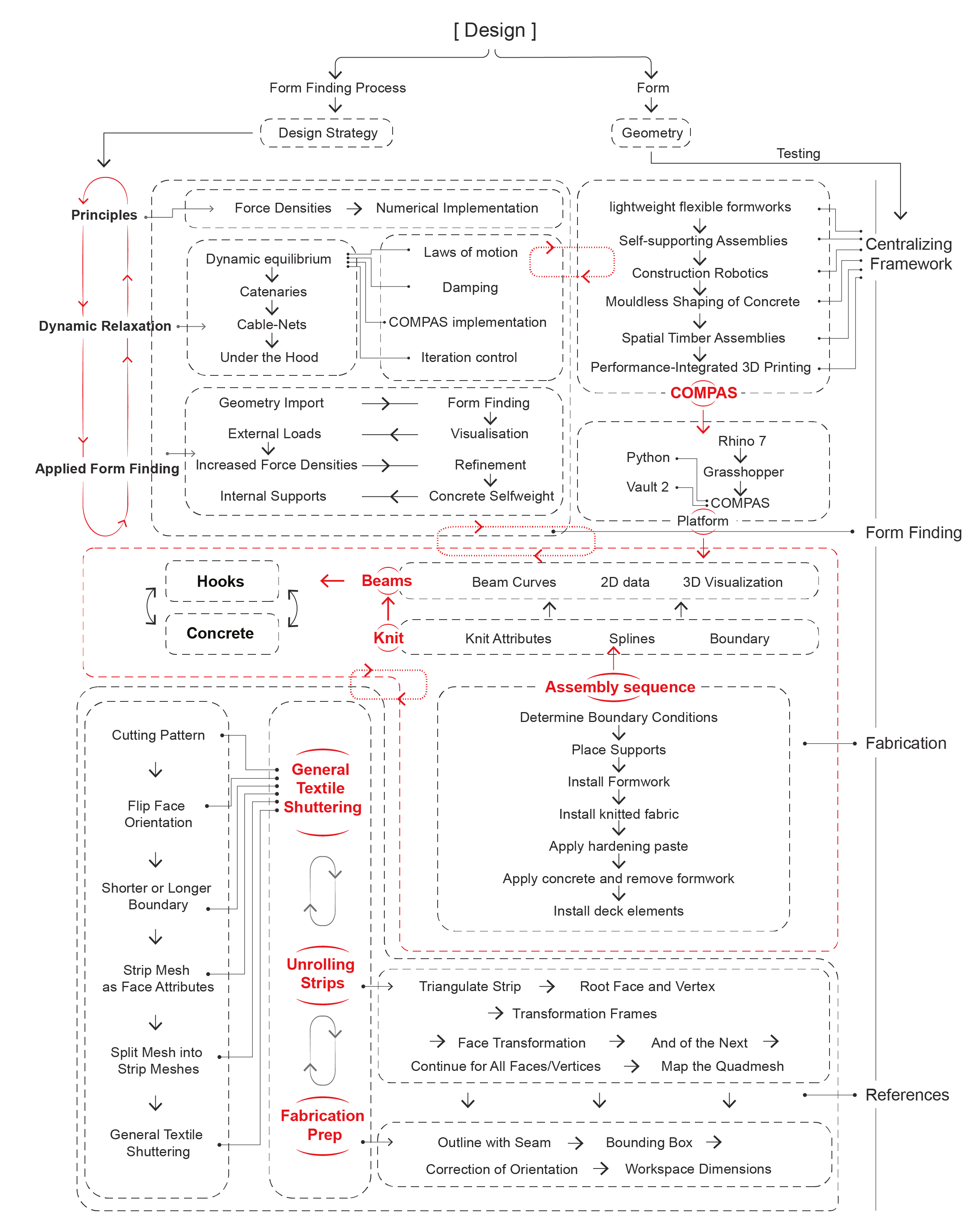
The design and construction of the bridge is divided into three layers, which respectively are steel frame, shell and tread. First, design the 3D printing form, determine the anchor points according to the terrain, then determine the steel frame structure line to generate the tensioning surface, then determine the construction sequence: decompose the steel frame and customize, use UHPC pouring in the cloth test to determine the amount of concrete, design the base and cloth. In the fabric design, first of all, to carry out tensile ability test, make machine weaving drawings to control the robot weaving.
Design Workflow
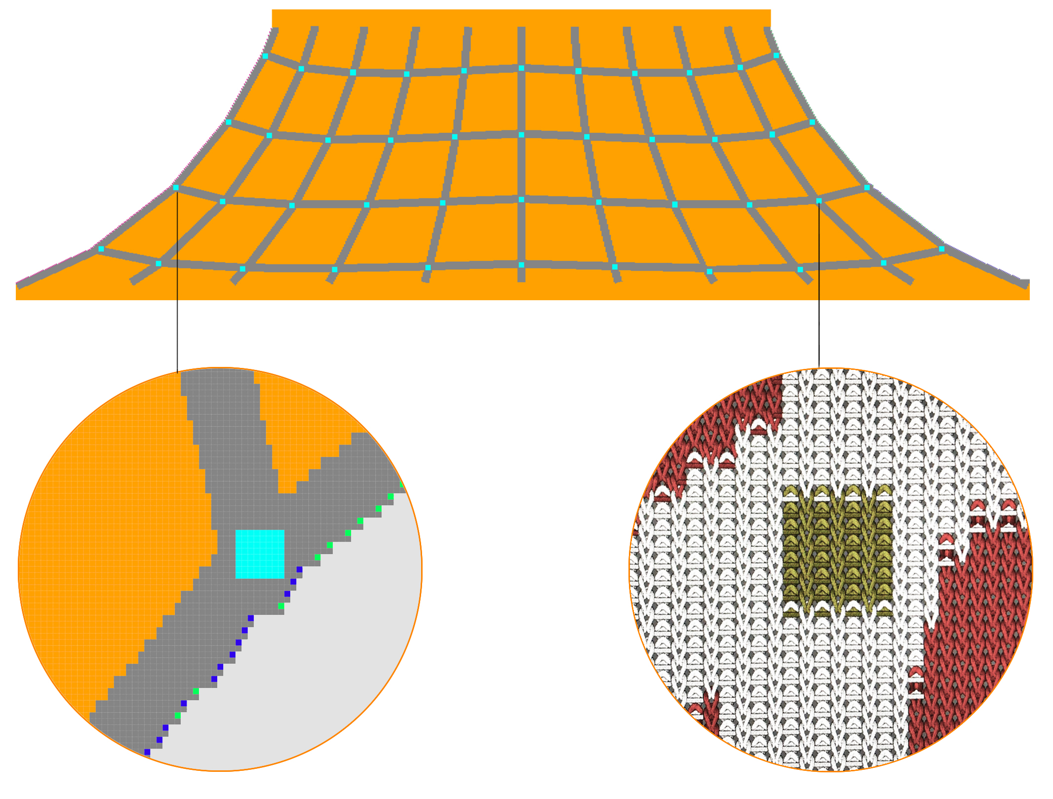
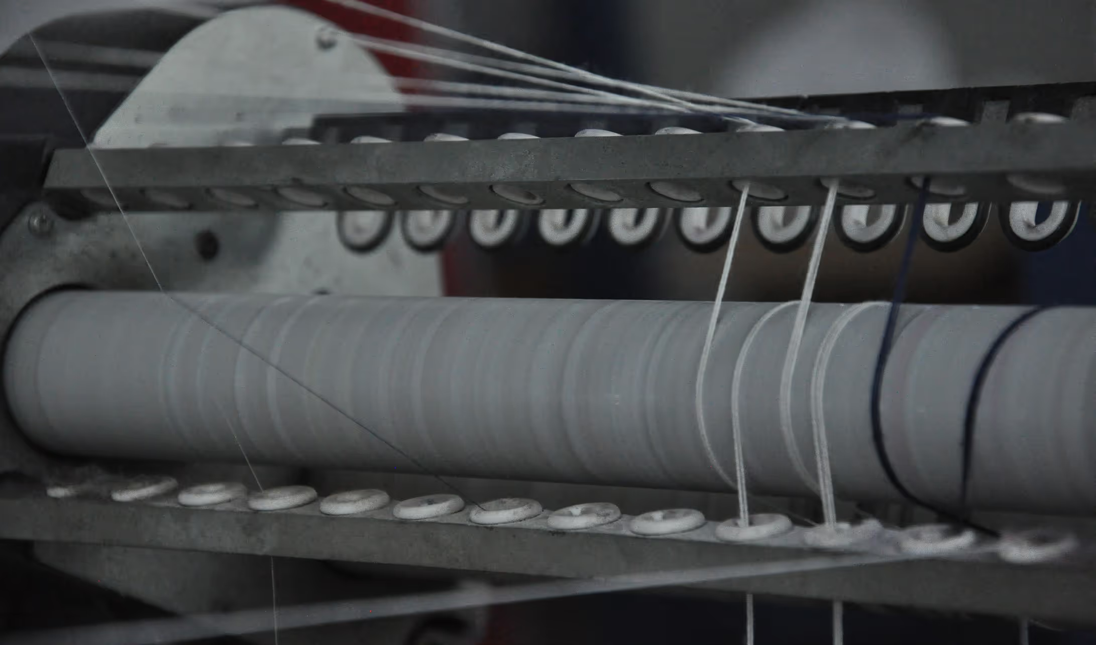
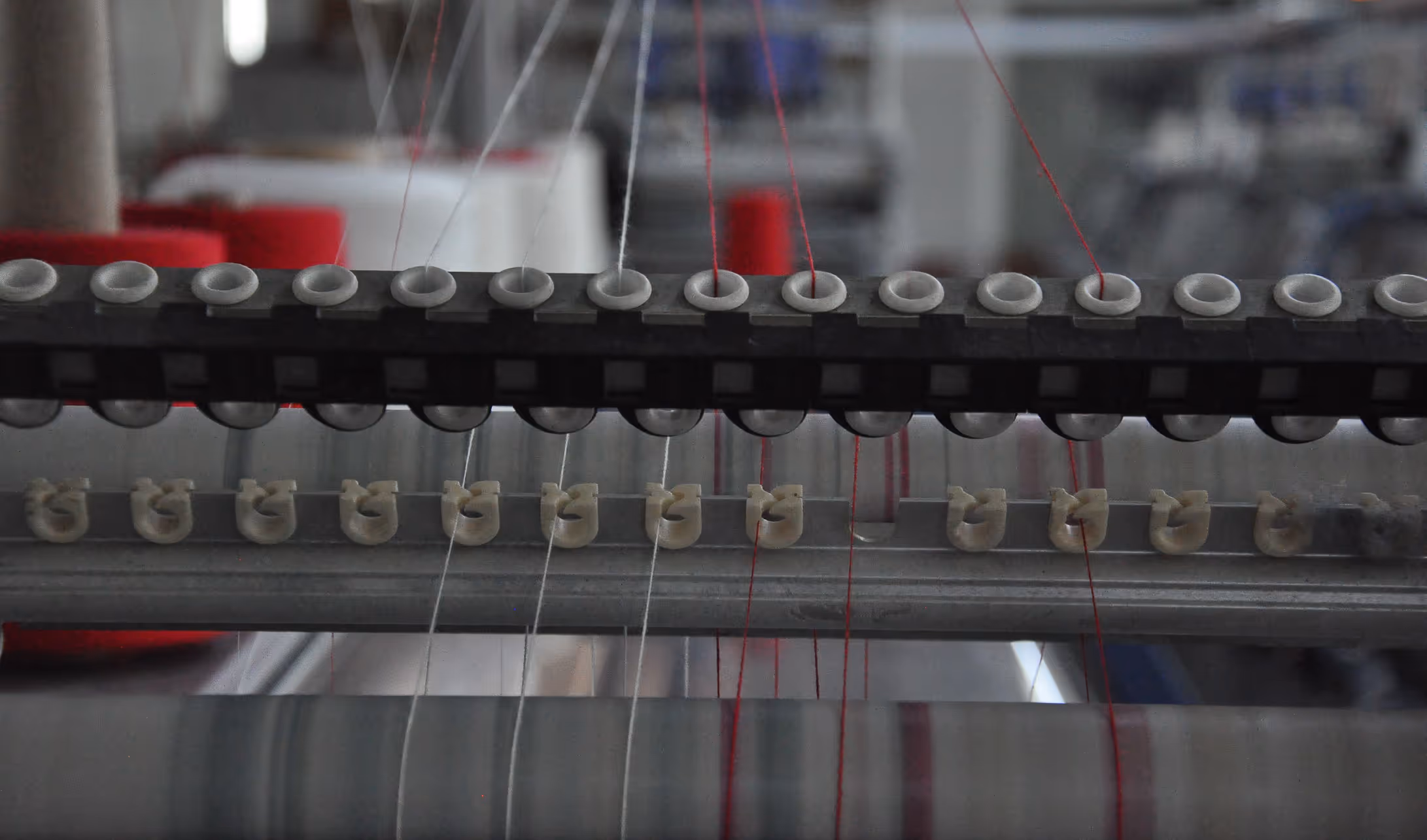
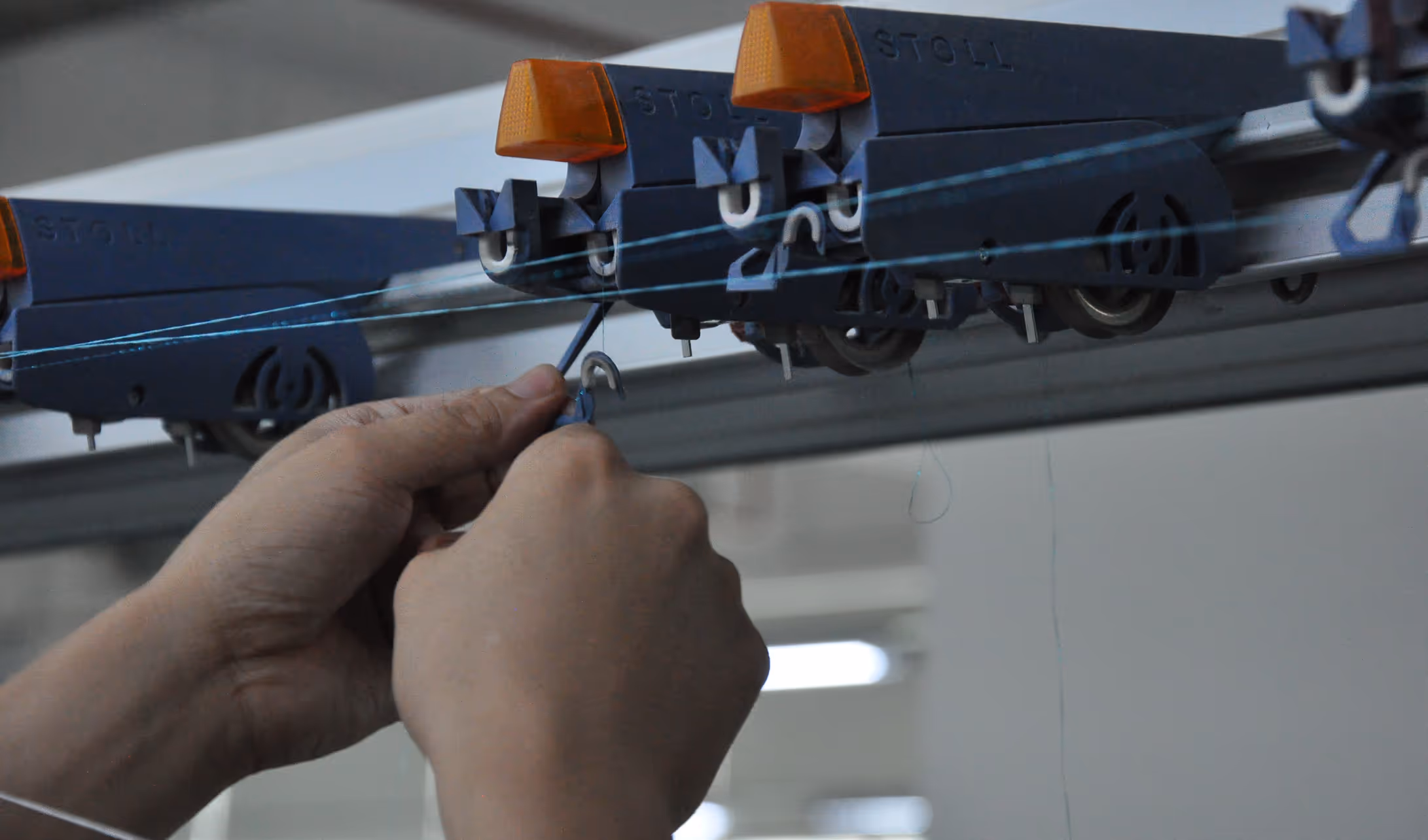
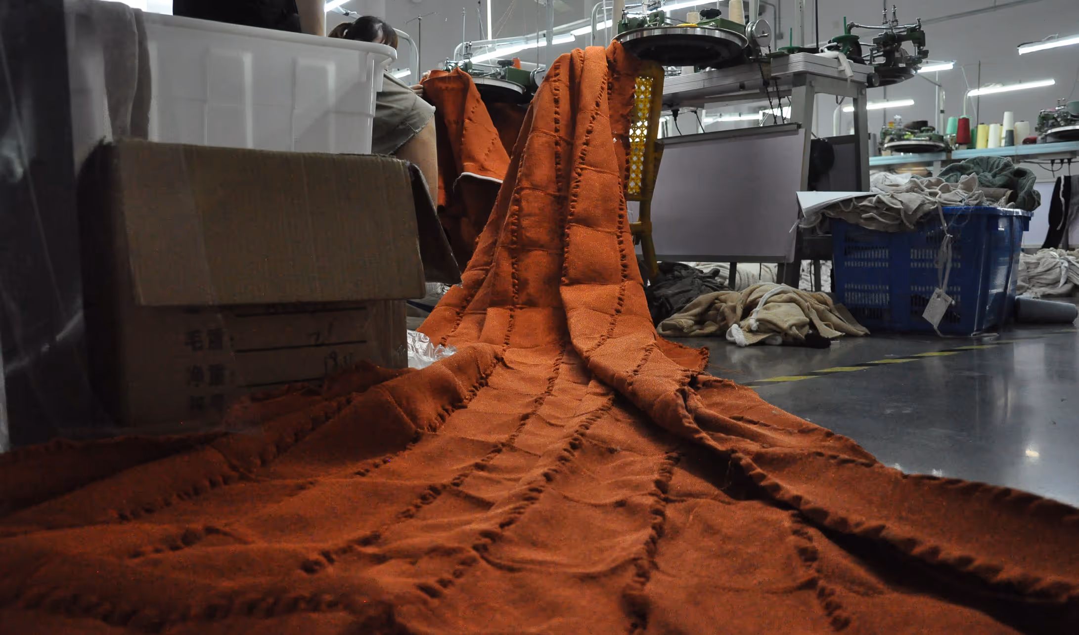
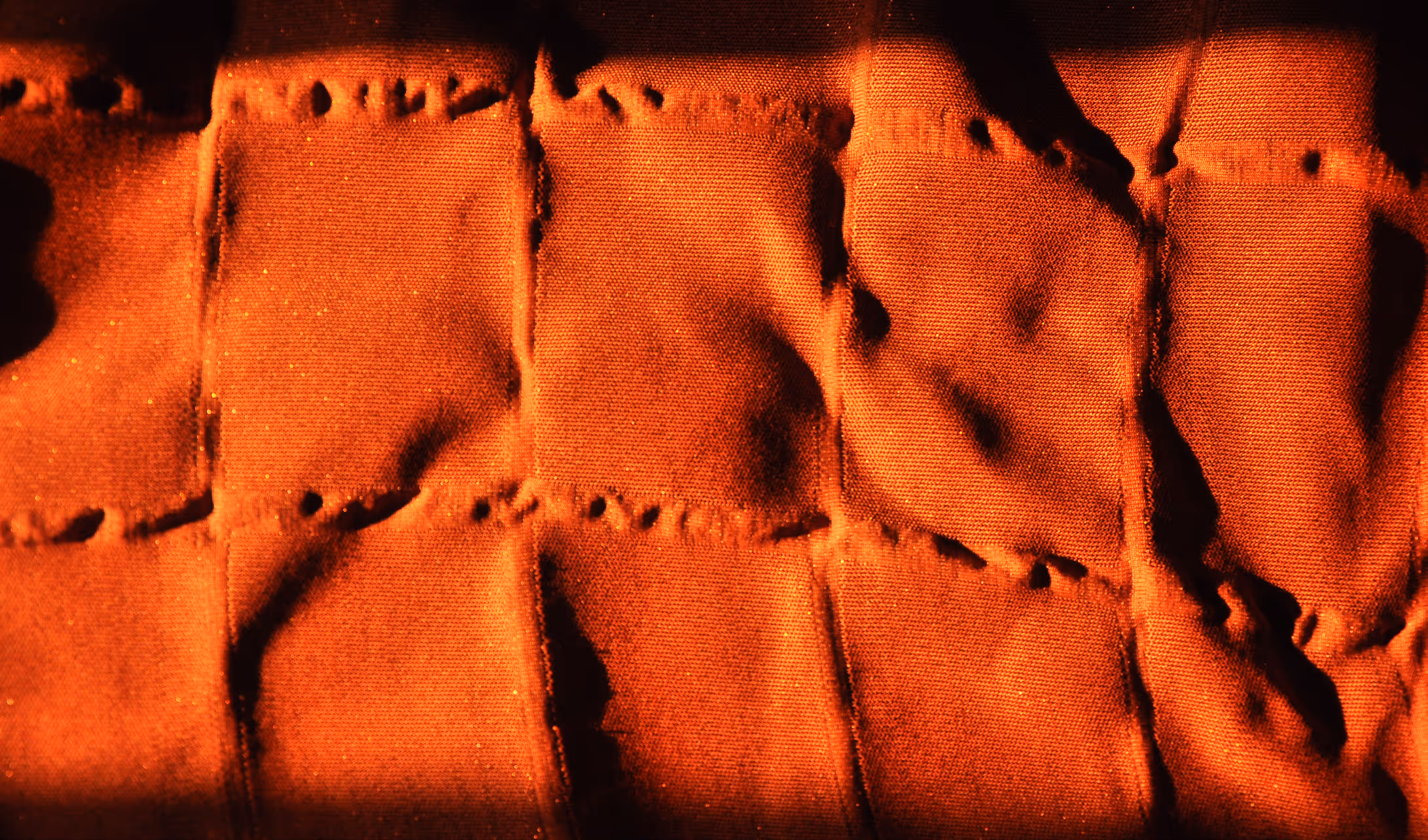
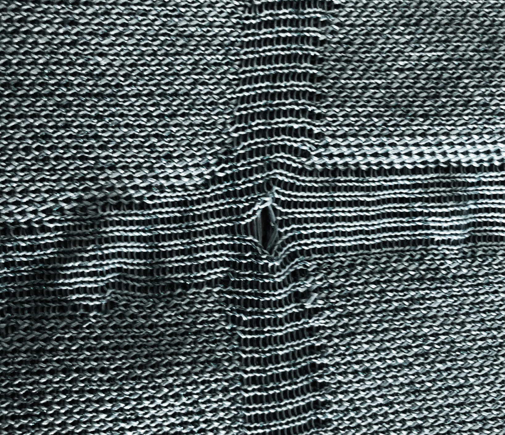
Research on Fabric Weaving Techniques
Different Weaving Methods : (a) orthogonal weaving; (b) skew weaving; (c) weft knitting; (d) Non-woven weaving
Knitting Control : (a) coil addition; (b) coil reduction; (c) short line weaving
Knitting Control : (a) coil addition; (b) coil reduction; (c) short line weaving
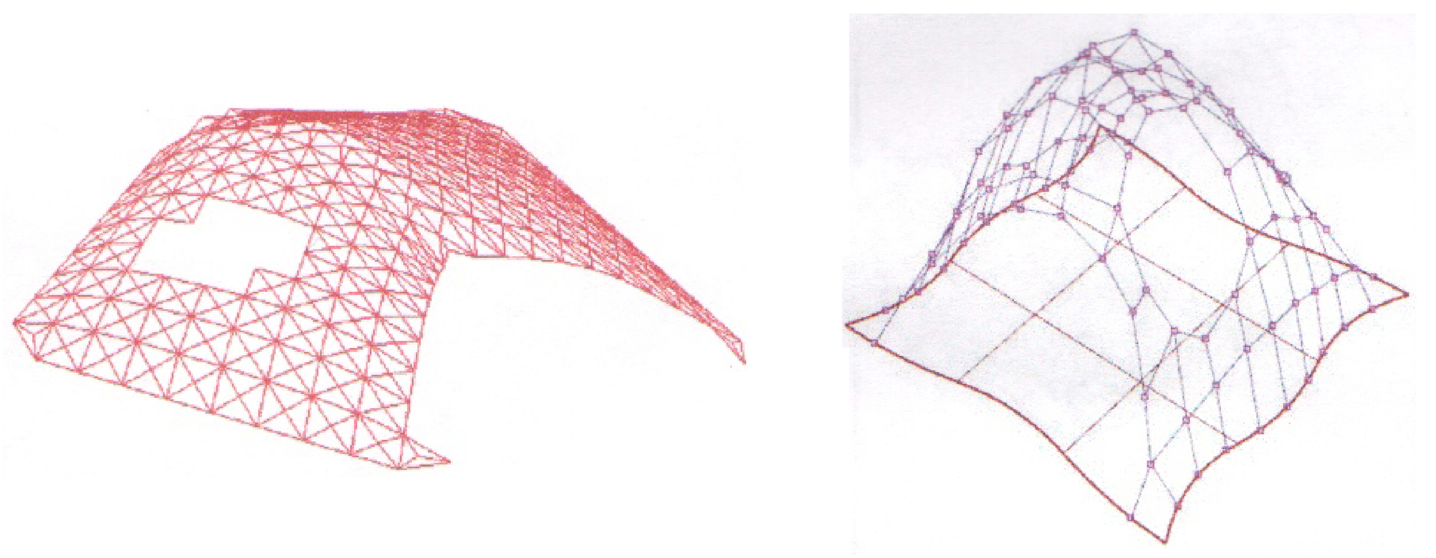
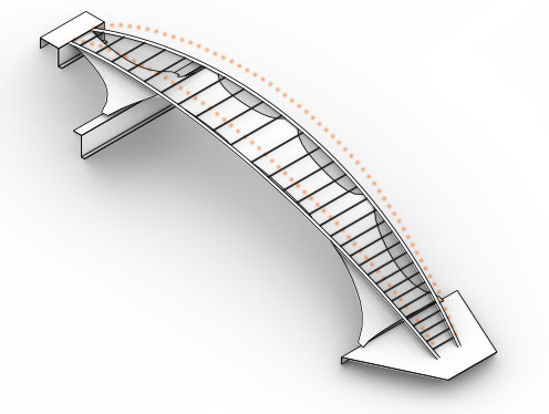
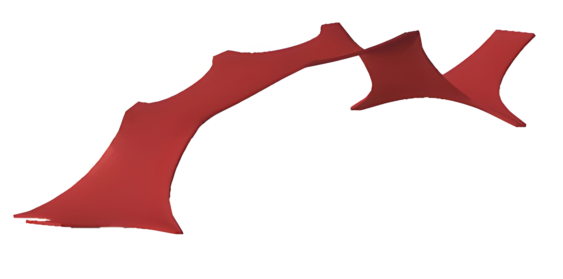
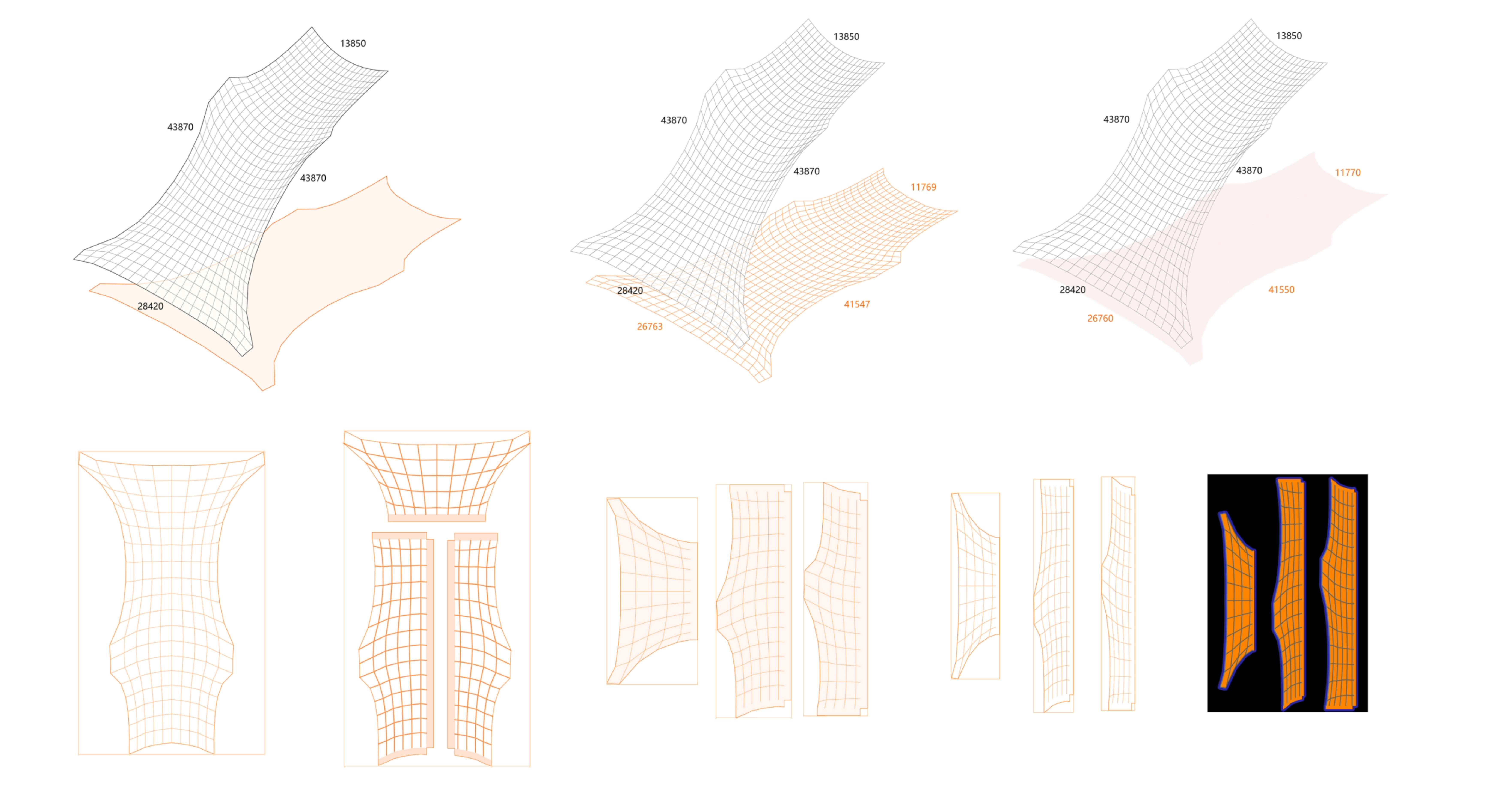
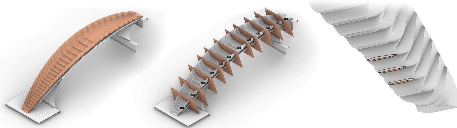
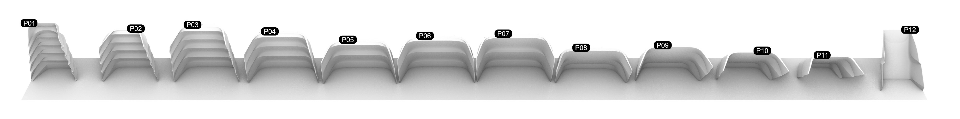
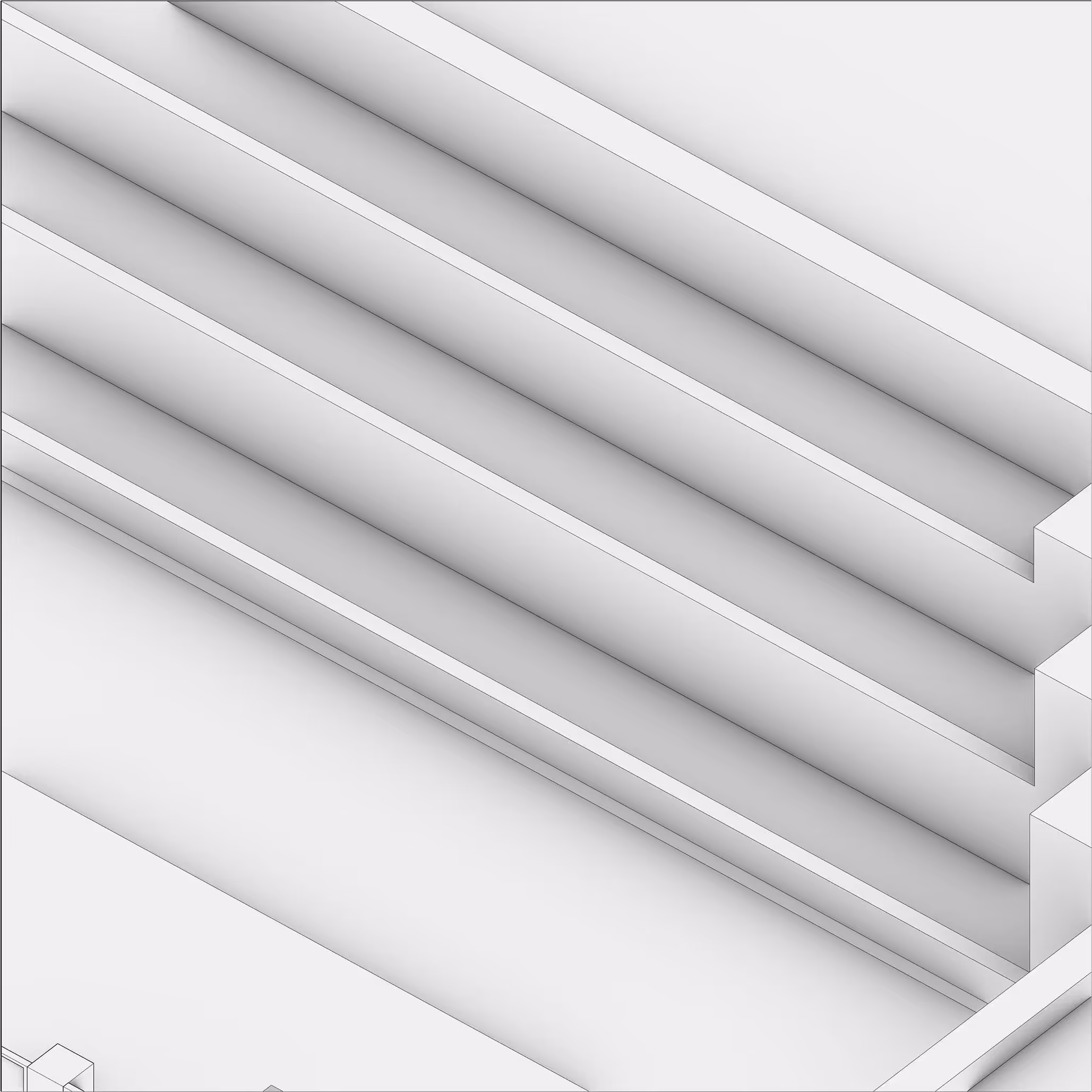
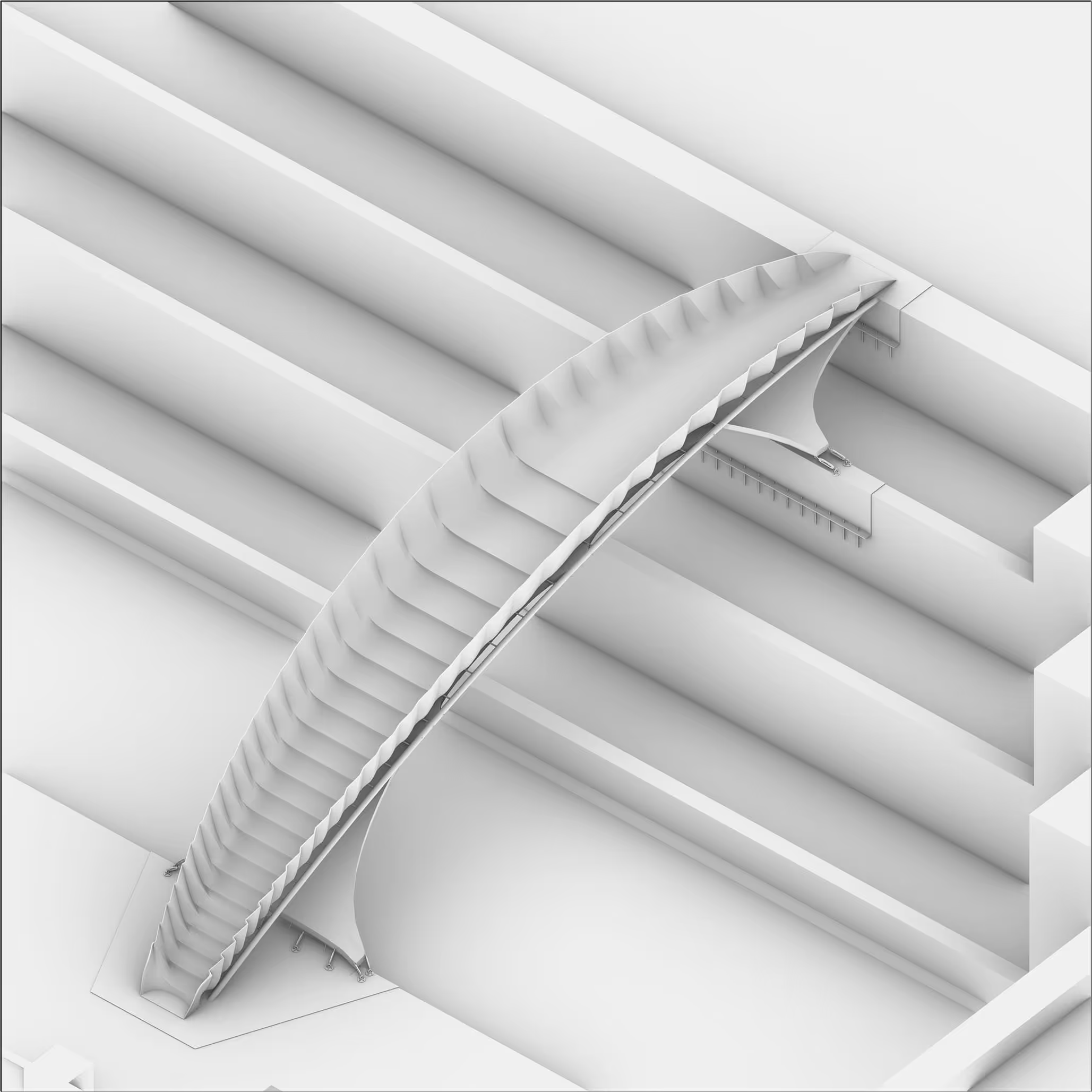
Generation of Curved Shell Structures

Generate handrail profiles from steel frame lines
Form handrail and step surfaces from steel pipes
Folded form enables self-supporting handrail
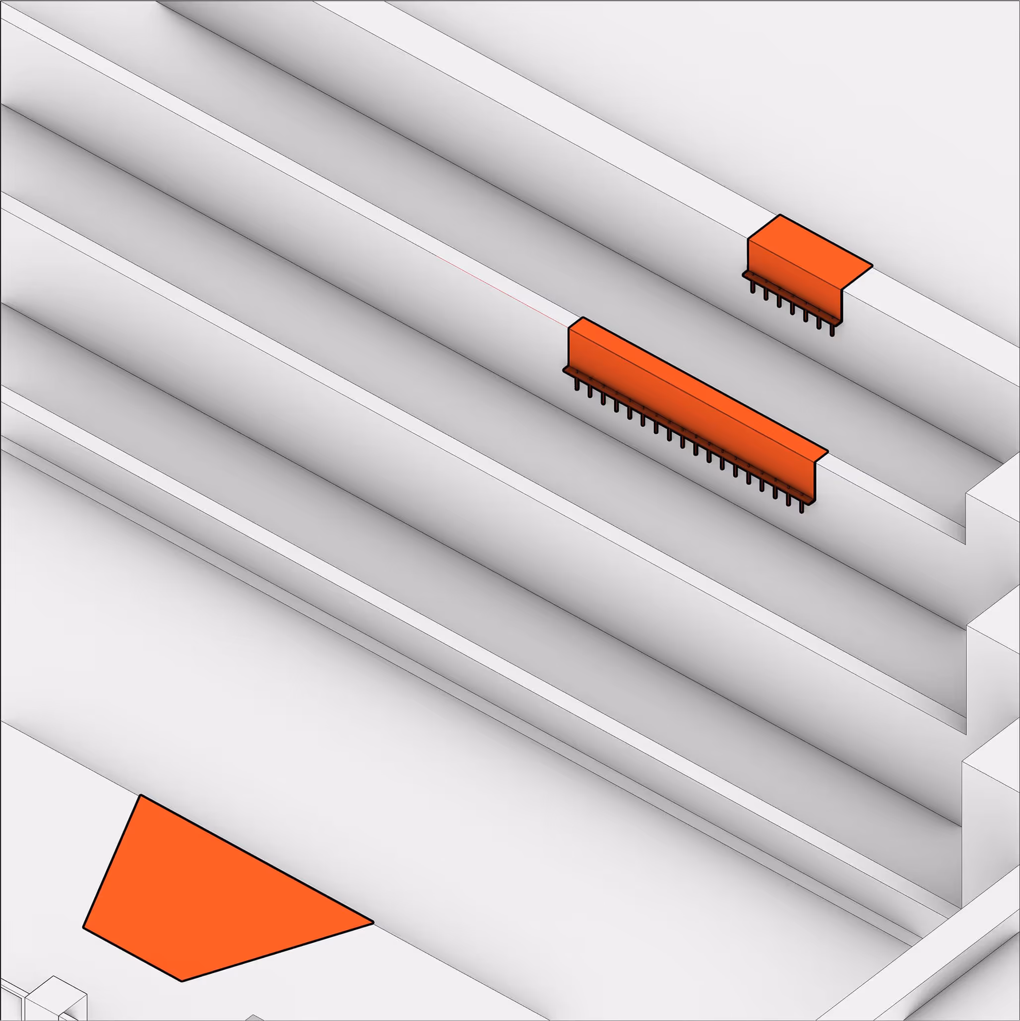
Bridge Deck Shell Generation
Handrail profiles from steel-frame control lines
Handrail and step surfaces from steel pipes
Folded form for self-supporting handrail
Material and Construction Detail Design

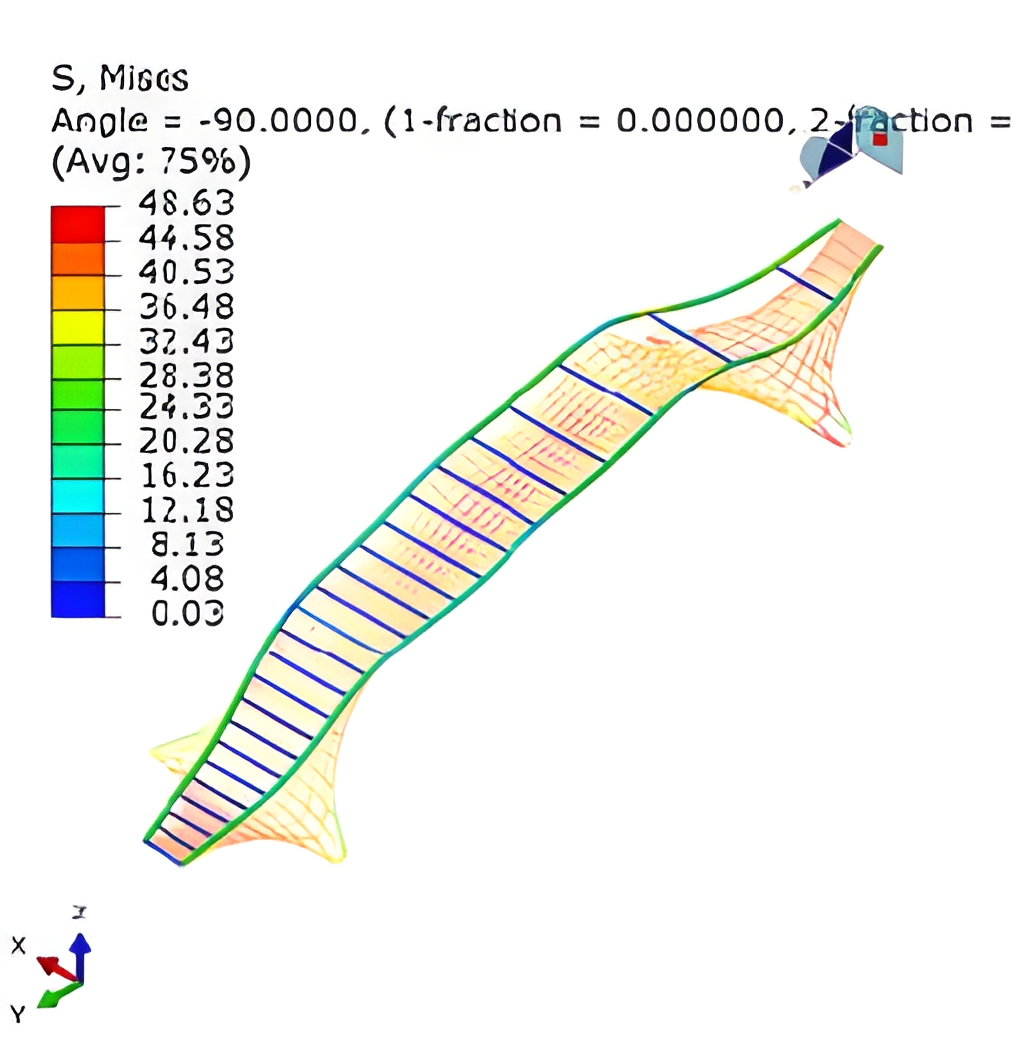
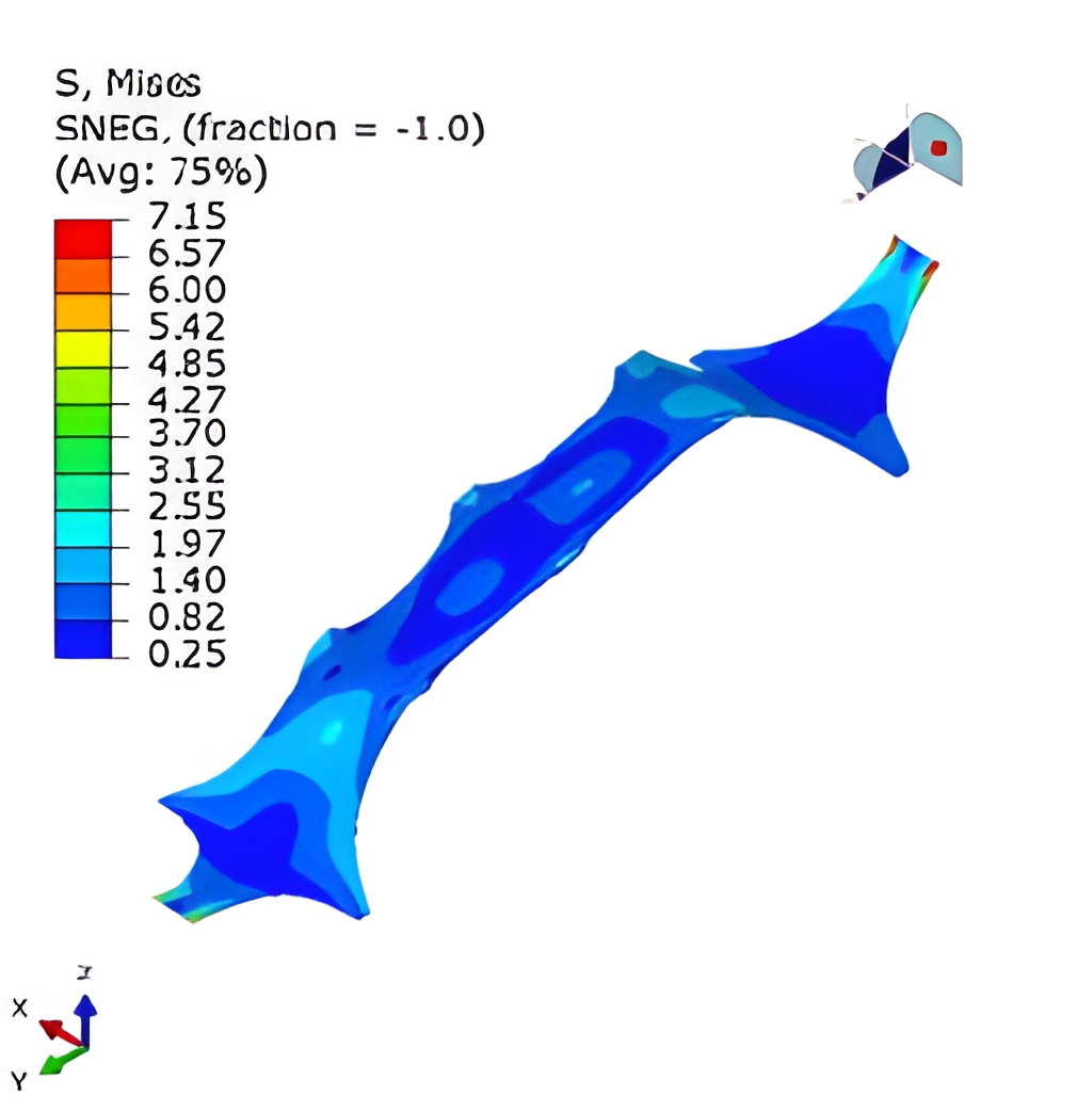
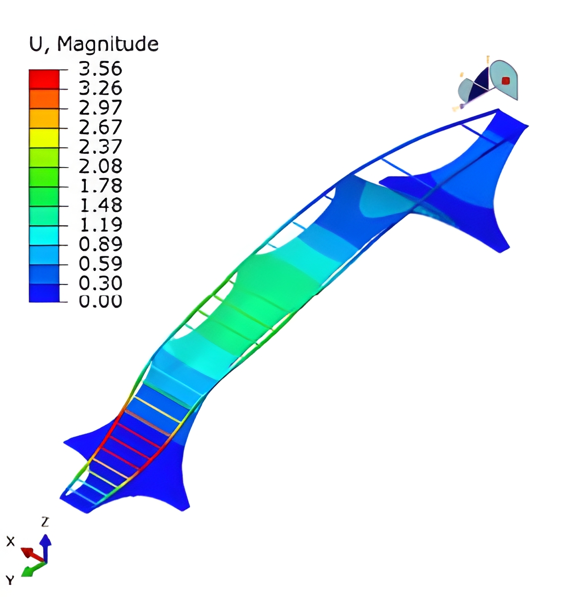
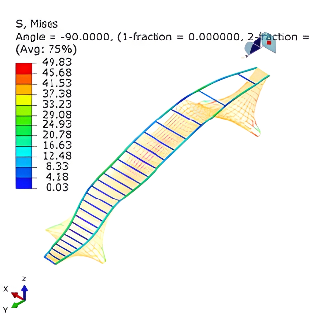
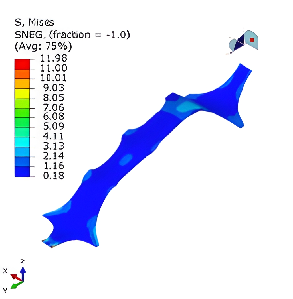
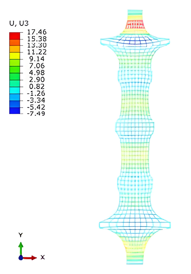
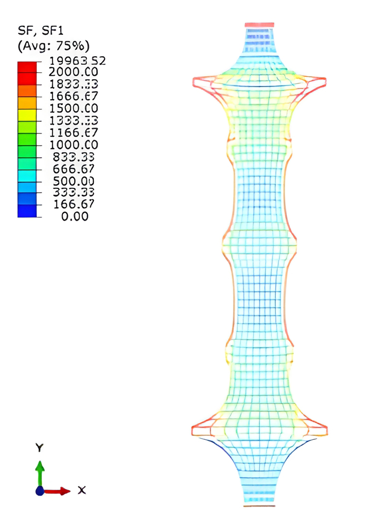
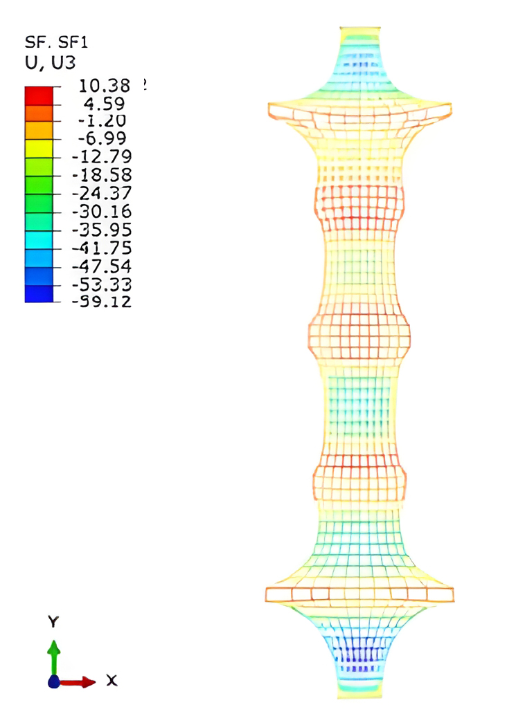
Loading Process & Calculation Results
Initial Geometry → Pre-tension Applied by Cooling → UHPC Self-Weight → Additional Loads + Crowd Load
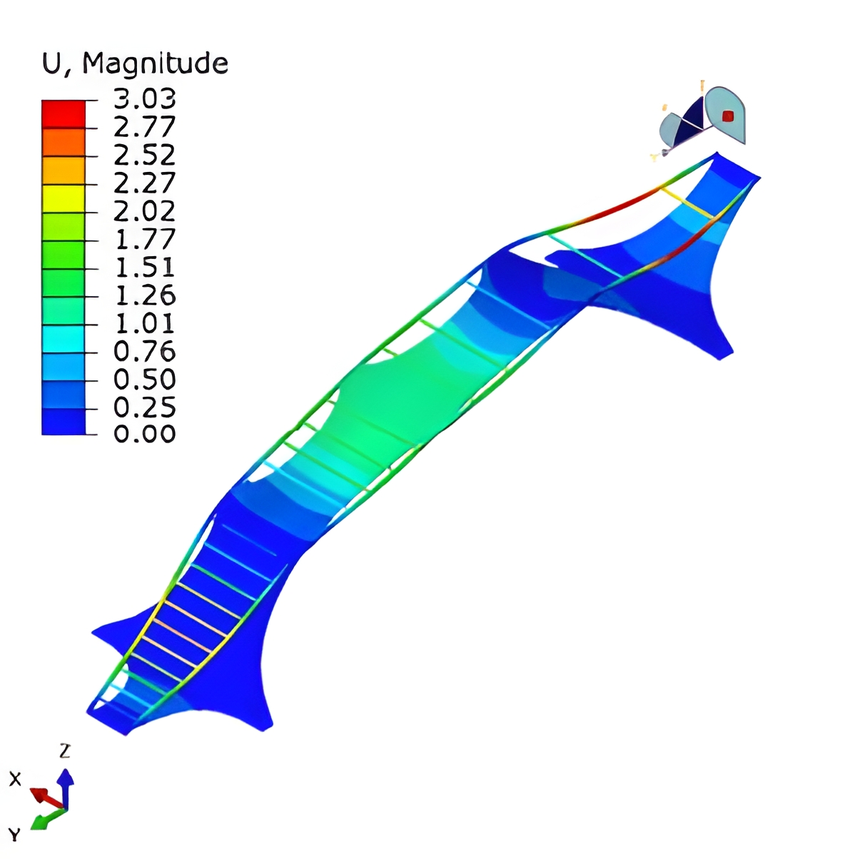
1.0 Dead Load + 1.0 Full-Span Live Load
1.3 Dead Load + 1.5 Full-Span Live Load
1.0 Dead Load + 1.0 Full-Span Live Load 1
1.3 Dead Load + 1.5 Full-Span Live Load 1
1.0 Dead Load + 1.0 Full-Span Live Load 2
1.3 Dead Load + 1.5 Full-Span Live Load 2
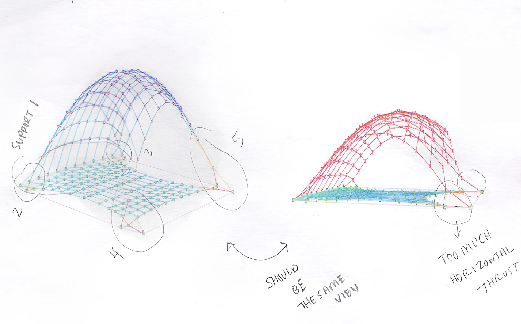
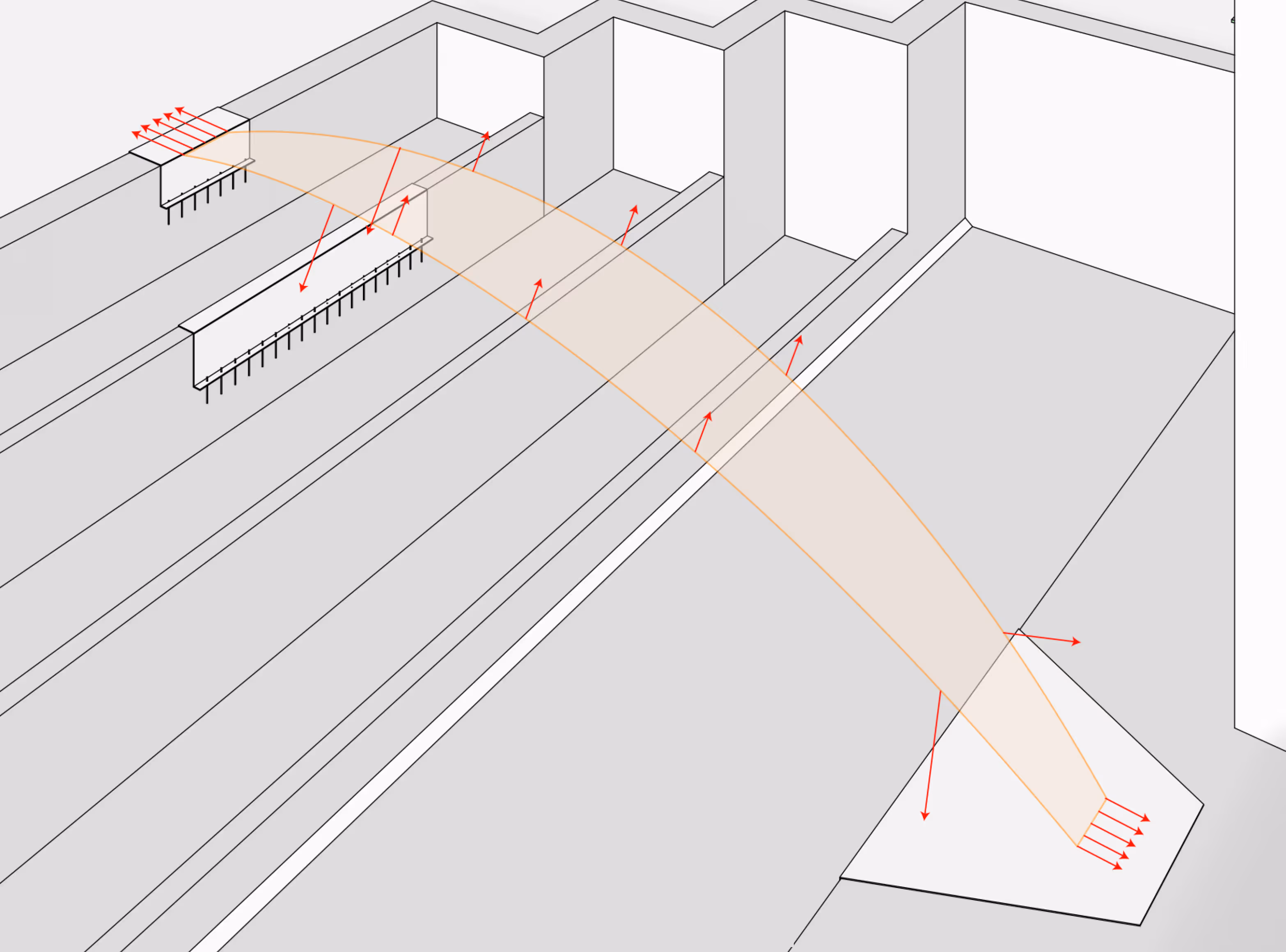
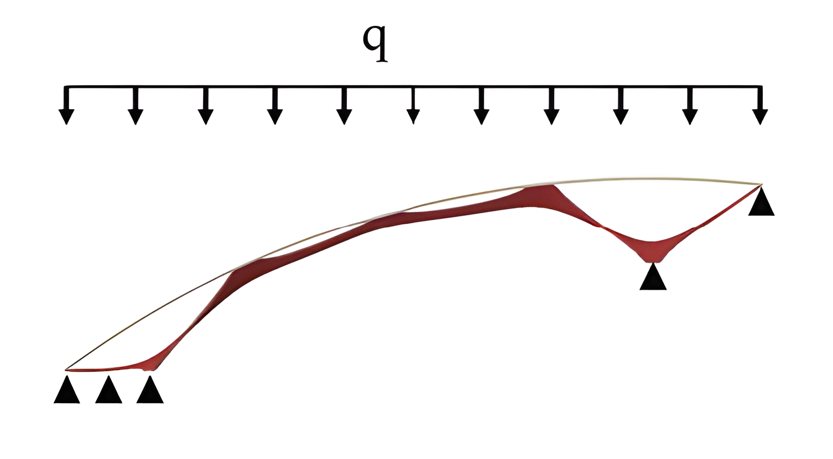
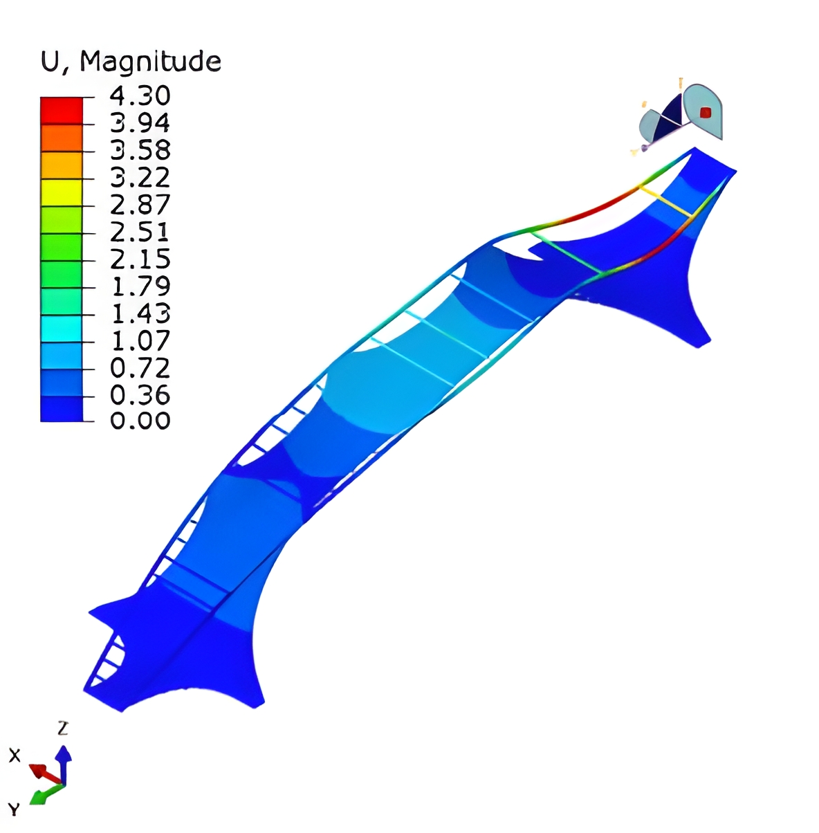
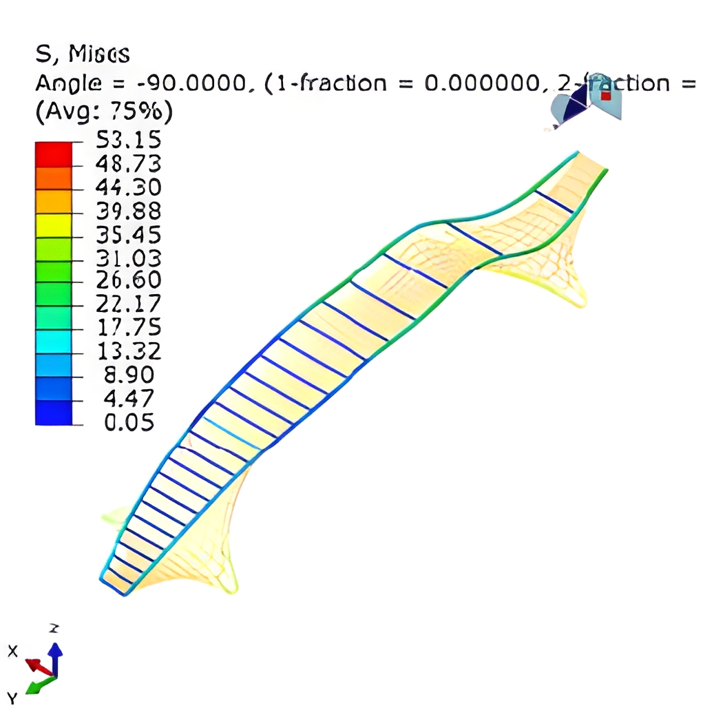
Cable Force and Deformation Analysis in Unhardened UHPC
Before tensioning, the steel frame must be fully fixed, and any deformation is not permitted. During the tensioning stage, the free-edge cables at mid-span remain slack. After the UHPC is cast—while still in its unhardened state—all cables are in tension, with the free-edge cables carrying higher pretension forces than the inner cables.Both the tensioning process and the UHPC casting will cause deformation of the cable net and increase the pretension forces; such deformation will not significantly decrease afterward. To reduce this deformation, a 1 cm layer of fast-setting mortar may be sprayed onto the cable net prior to UHPC casting.The Wen’s method provides only a qualitative simulation of the changes in cable forces and deformations during pretensioning, serving as guidance for construction and fabrication.
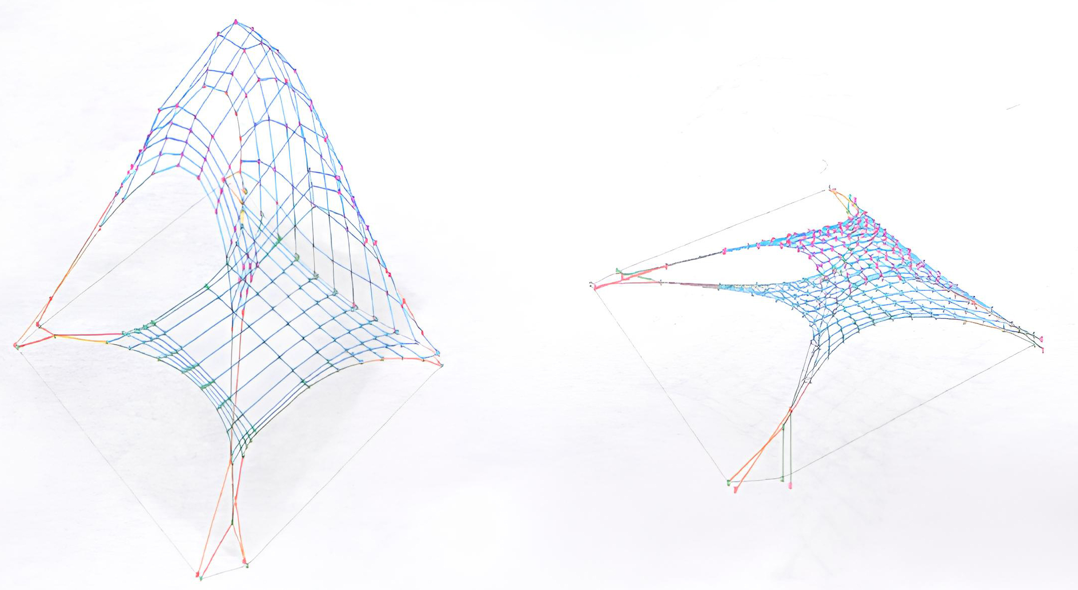
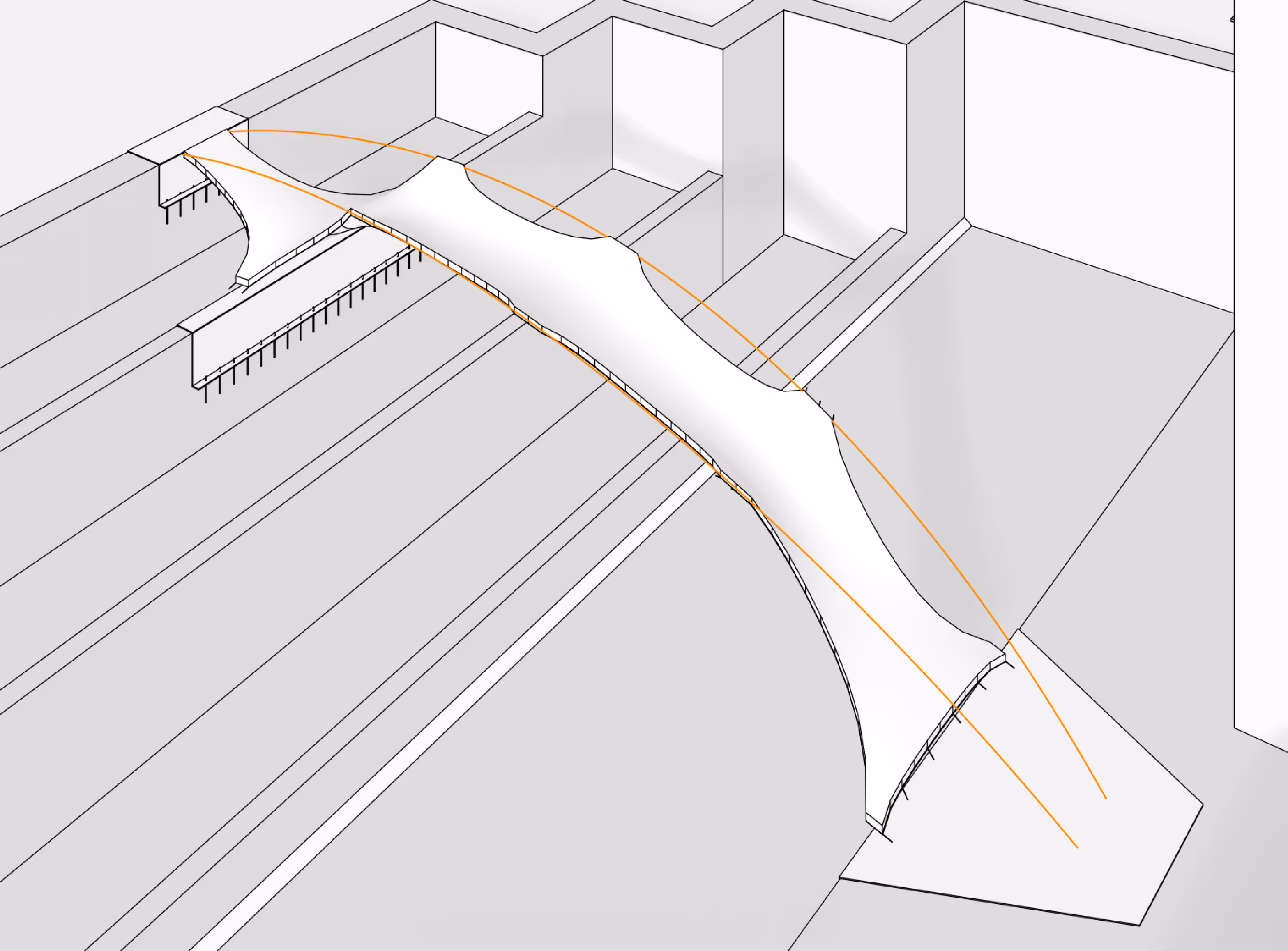
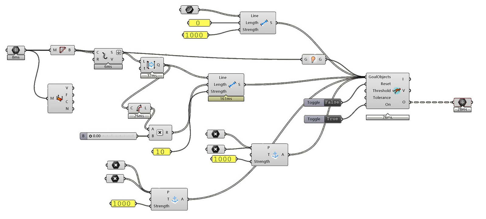
Simulating Cable Prestress Application Using the Cooling Method
Casting UHPC, Not Yet Hardened
CONCLUSION:
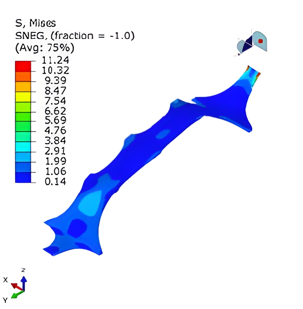
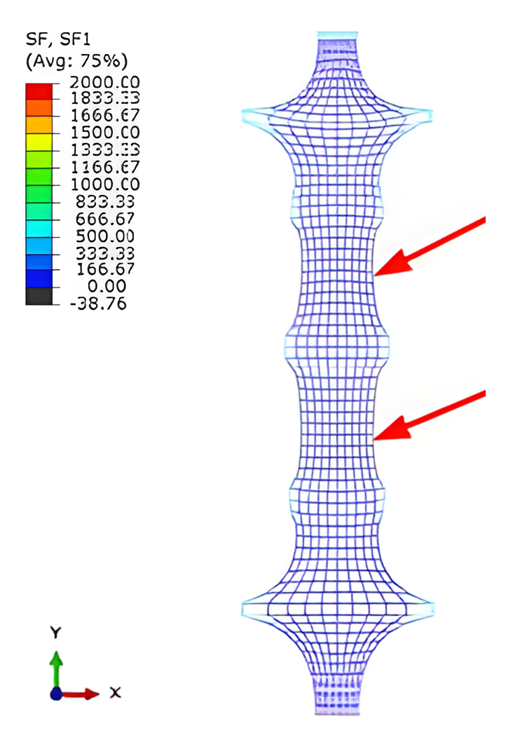
1. After the UHPC hardens, the structural system formed with the steel frame provides sufficient load-bearing capacity. Under the considered loads, both deformation and capacity meet service requirements.
2. Before tensioning the cable net, the steel frame must be fully fixed with supports, allowing no deformation. The supports should only be removed after the UHPC has hardened.
3. At the connections between the UHPC shell and the steel frame, as well as at both ends of the UHPC shell, it is recommended to use double-layer reinforcement of φ8@100. The reinforcement should be welded to the steel frame and anchored into the shell with a length of ≥500 mm.
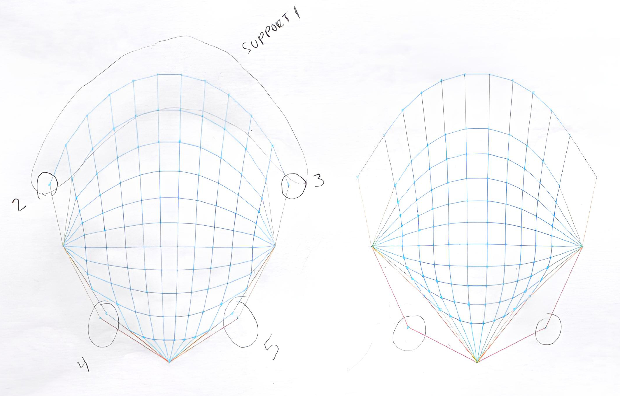
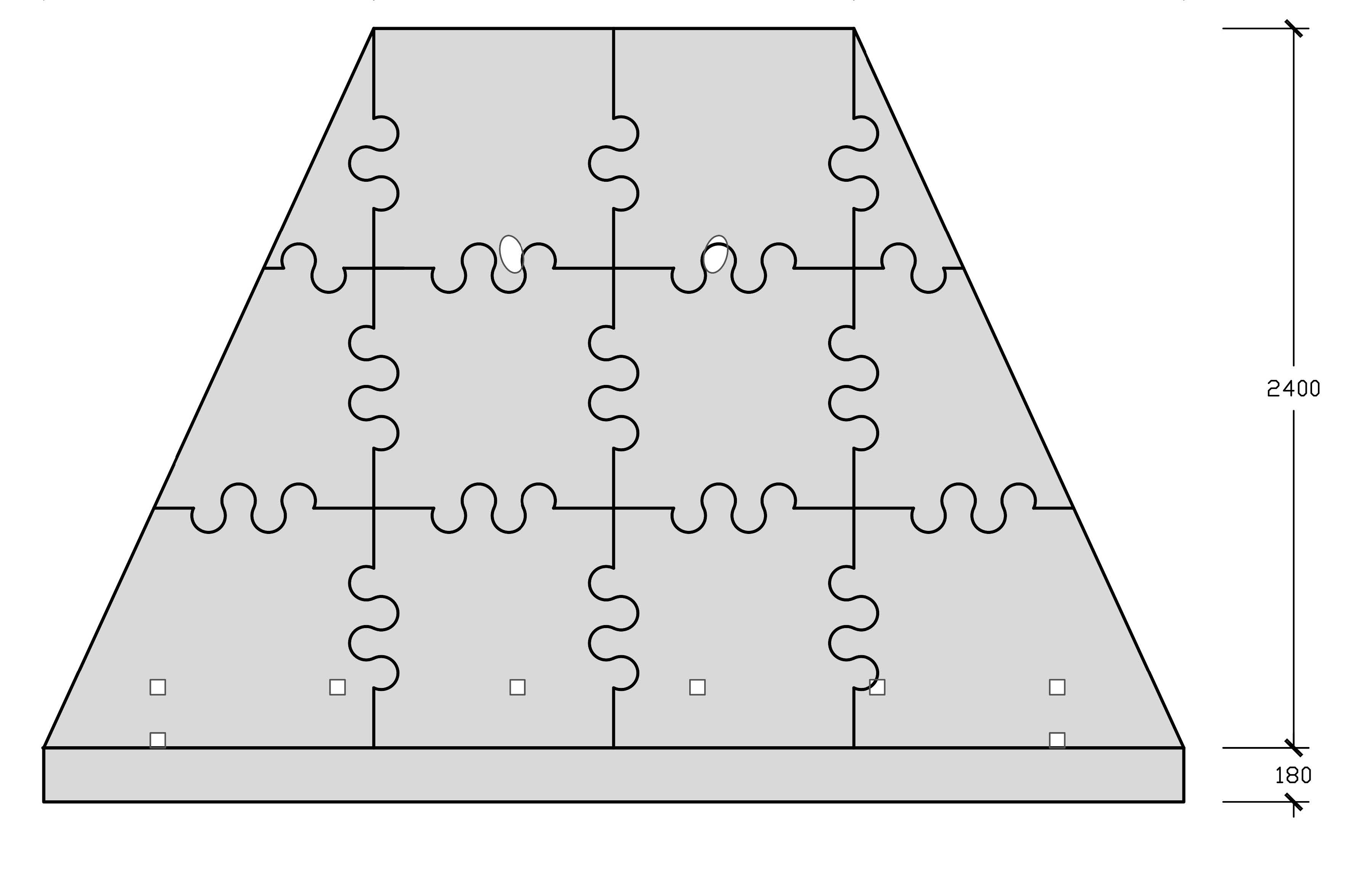
Support Analysis
Plan Development
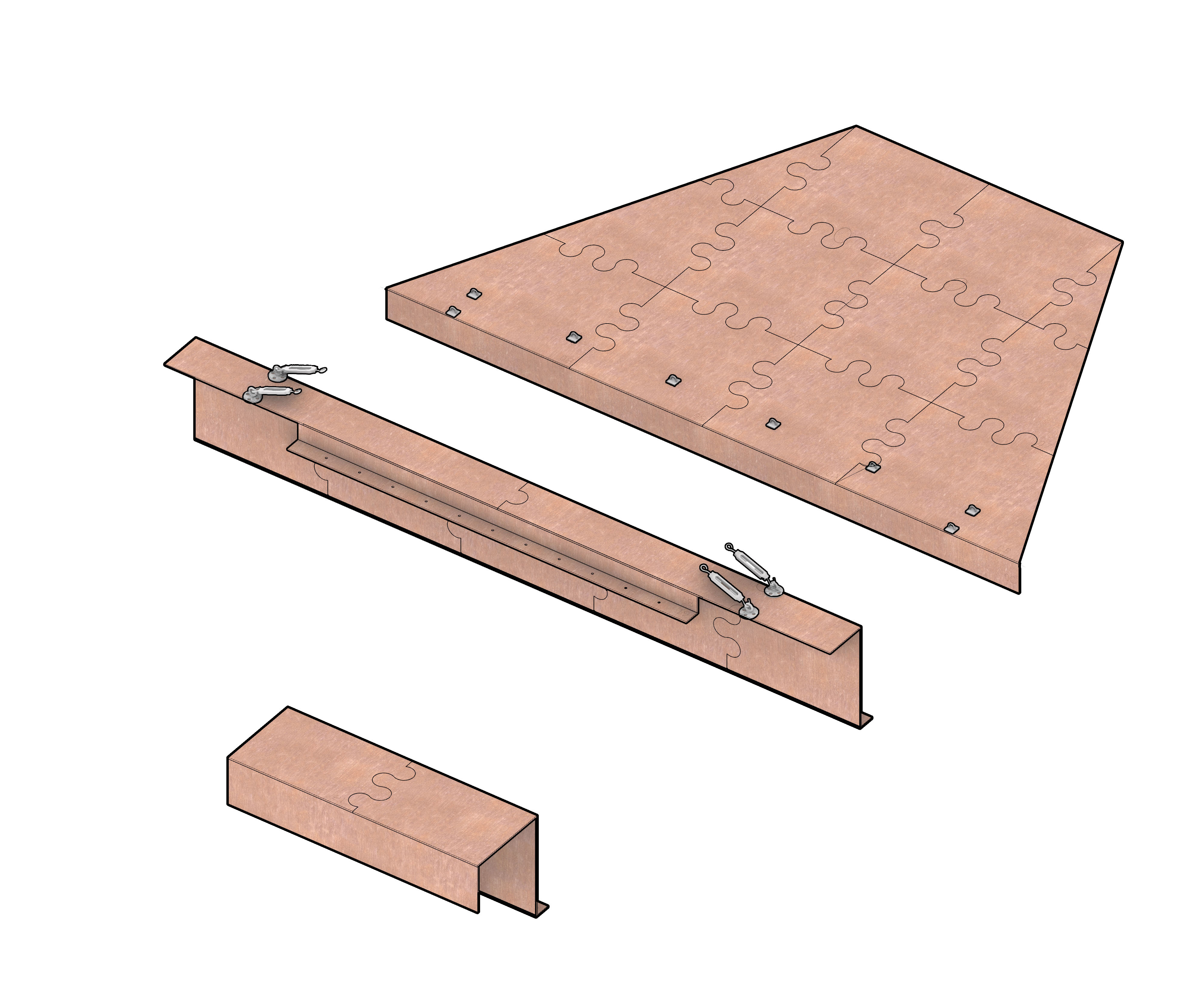
Axonometric view
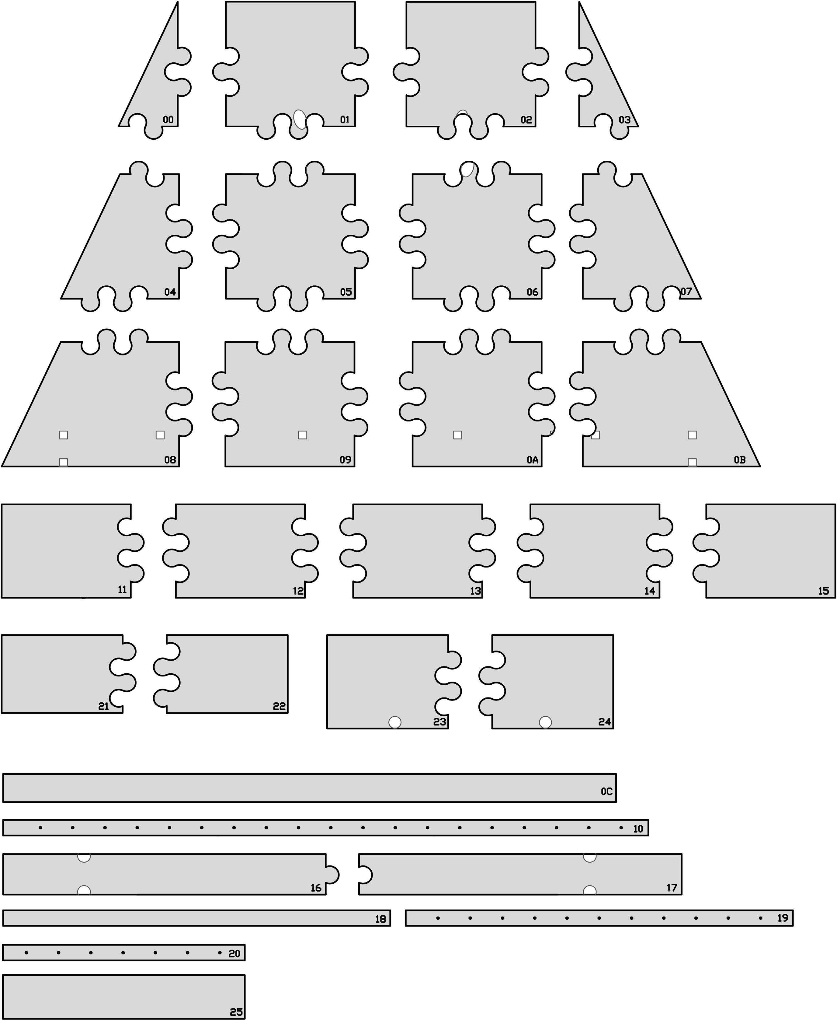
Laser Cutting Exploded Diagram
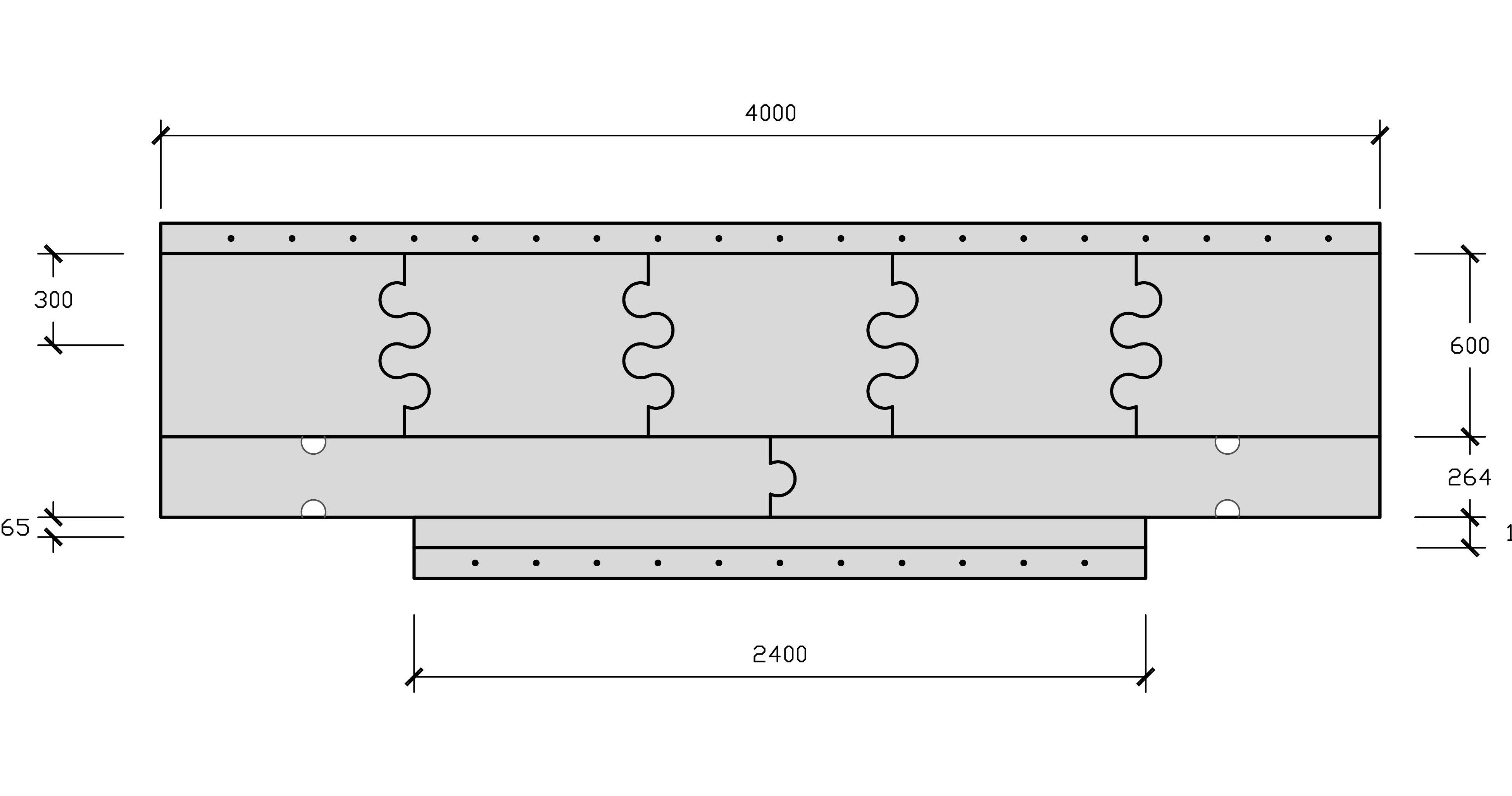
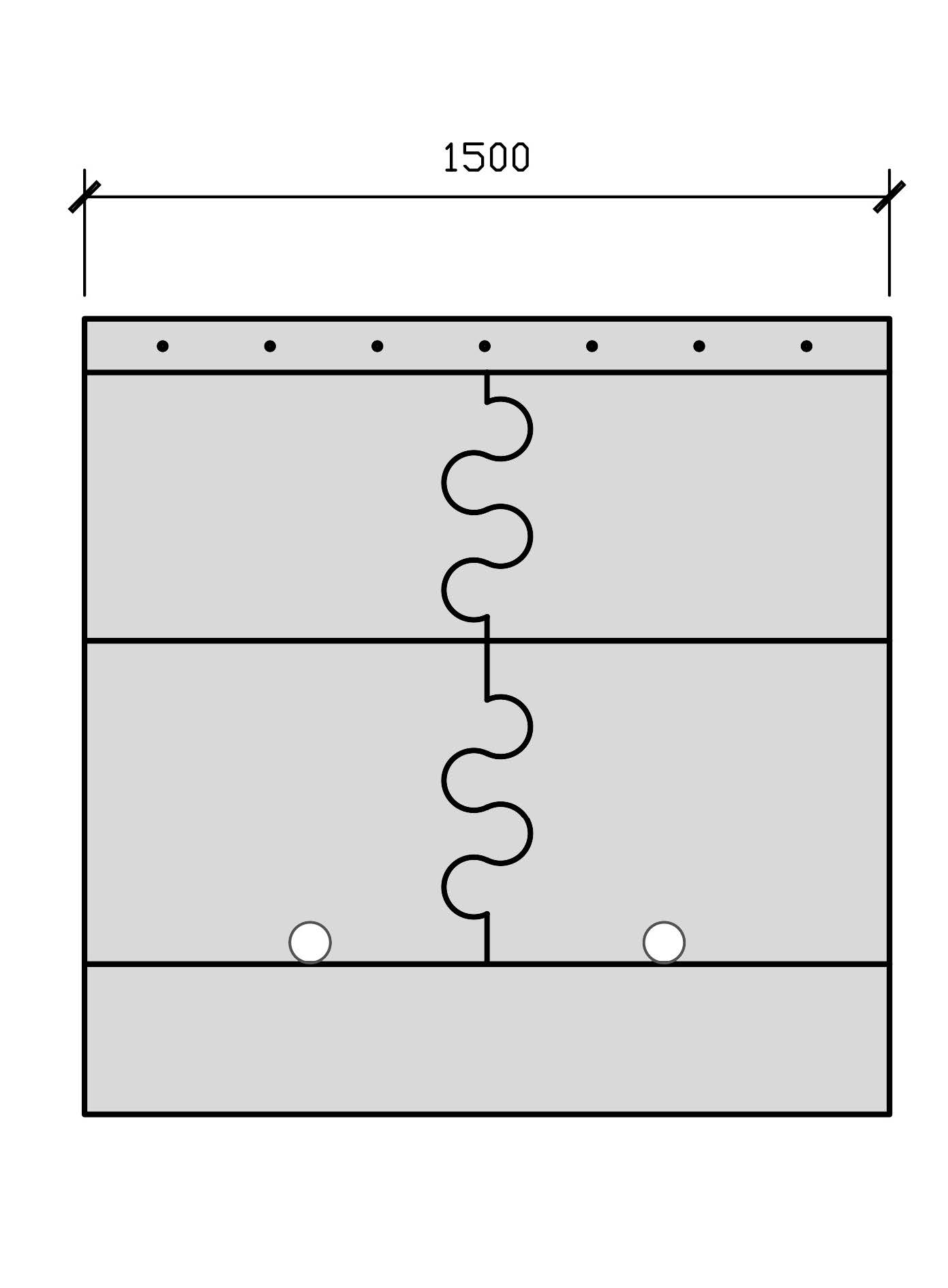
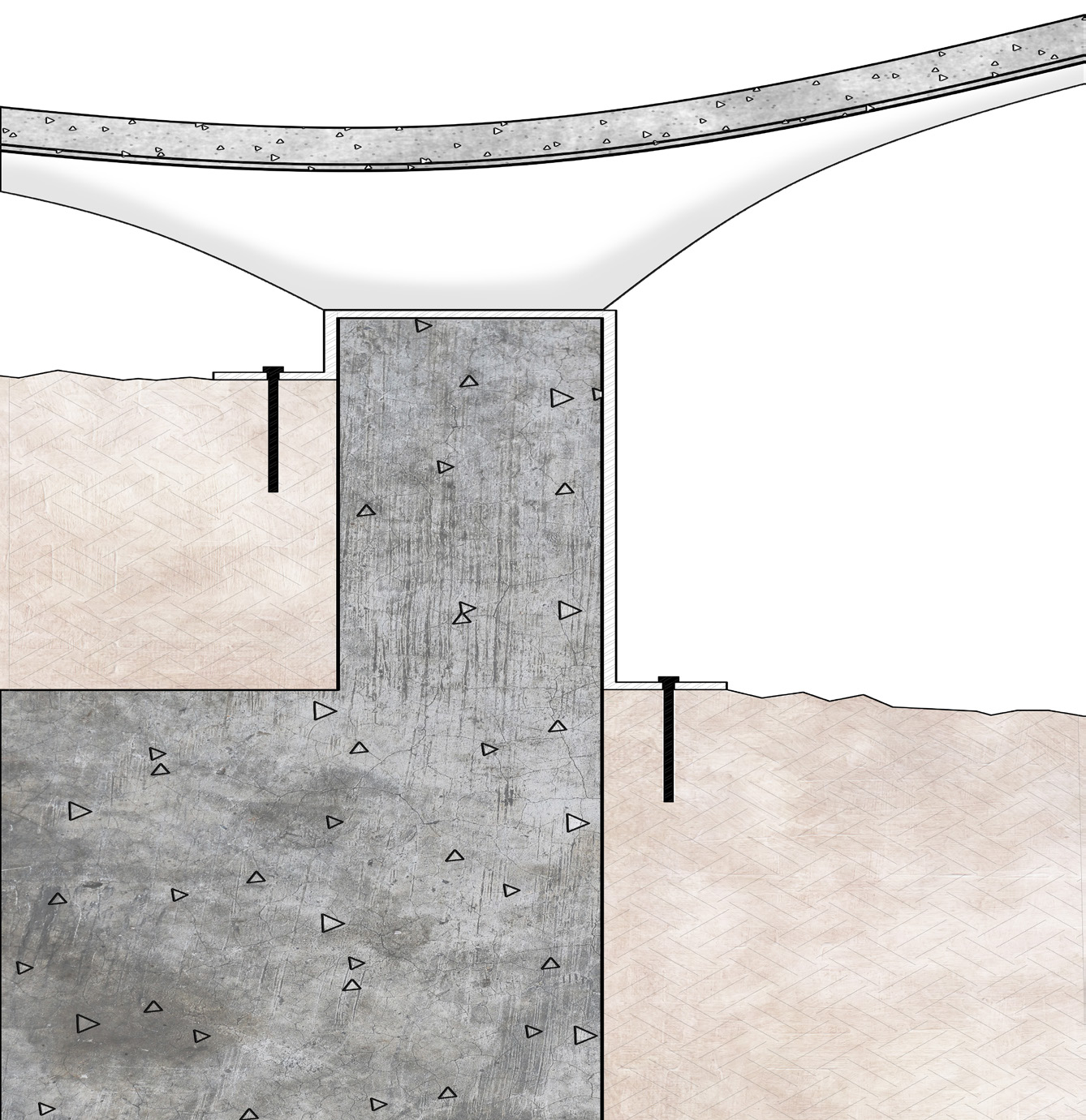
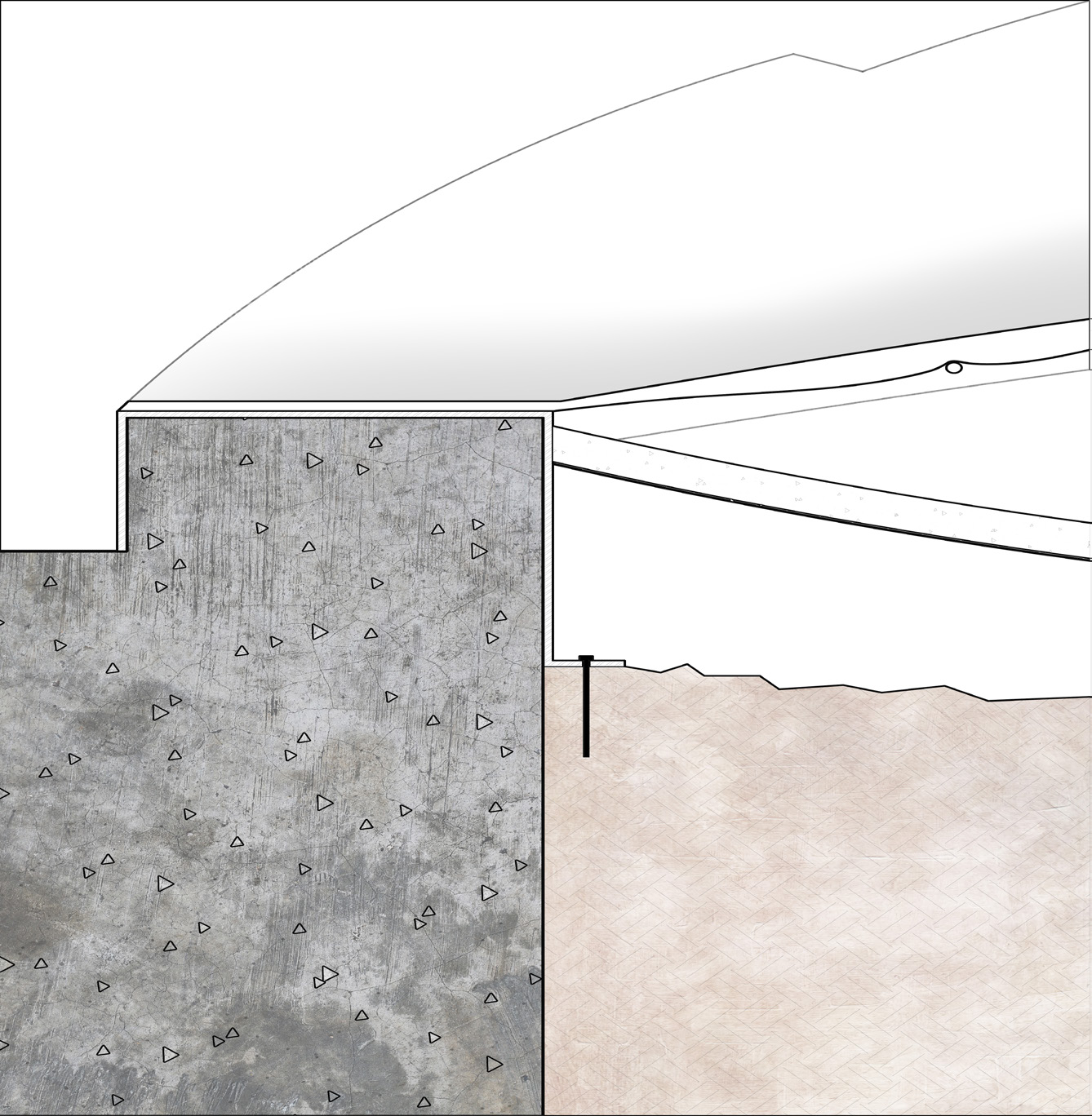
Section Drawing
Fabric Design, Fabrication, and Installation
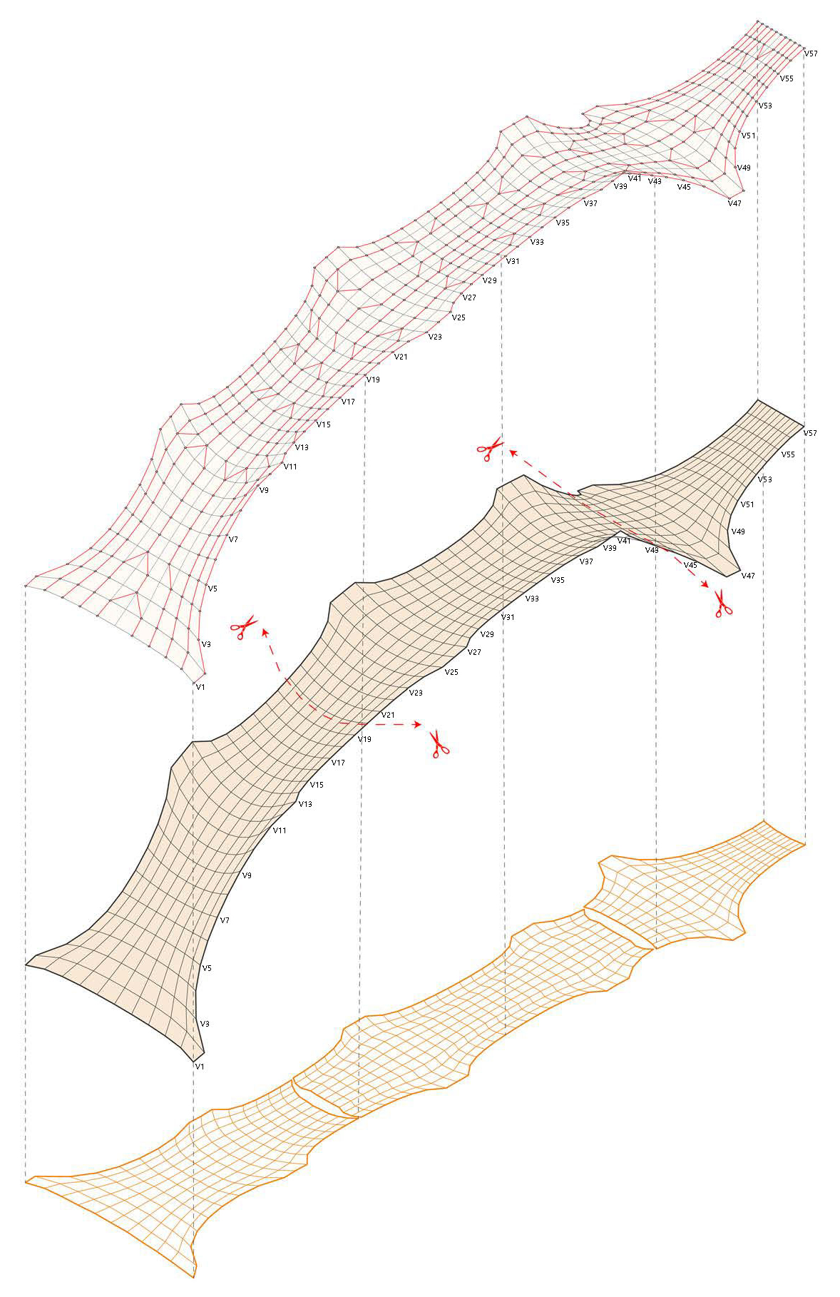
3D-to-2D Conversion
Weaving Logic Design
3D-Printed Bridge Deck Design
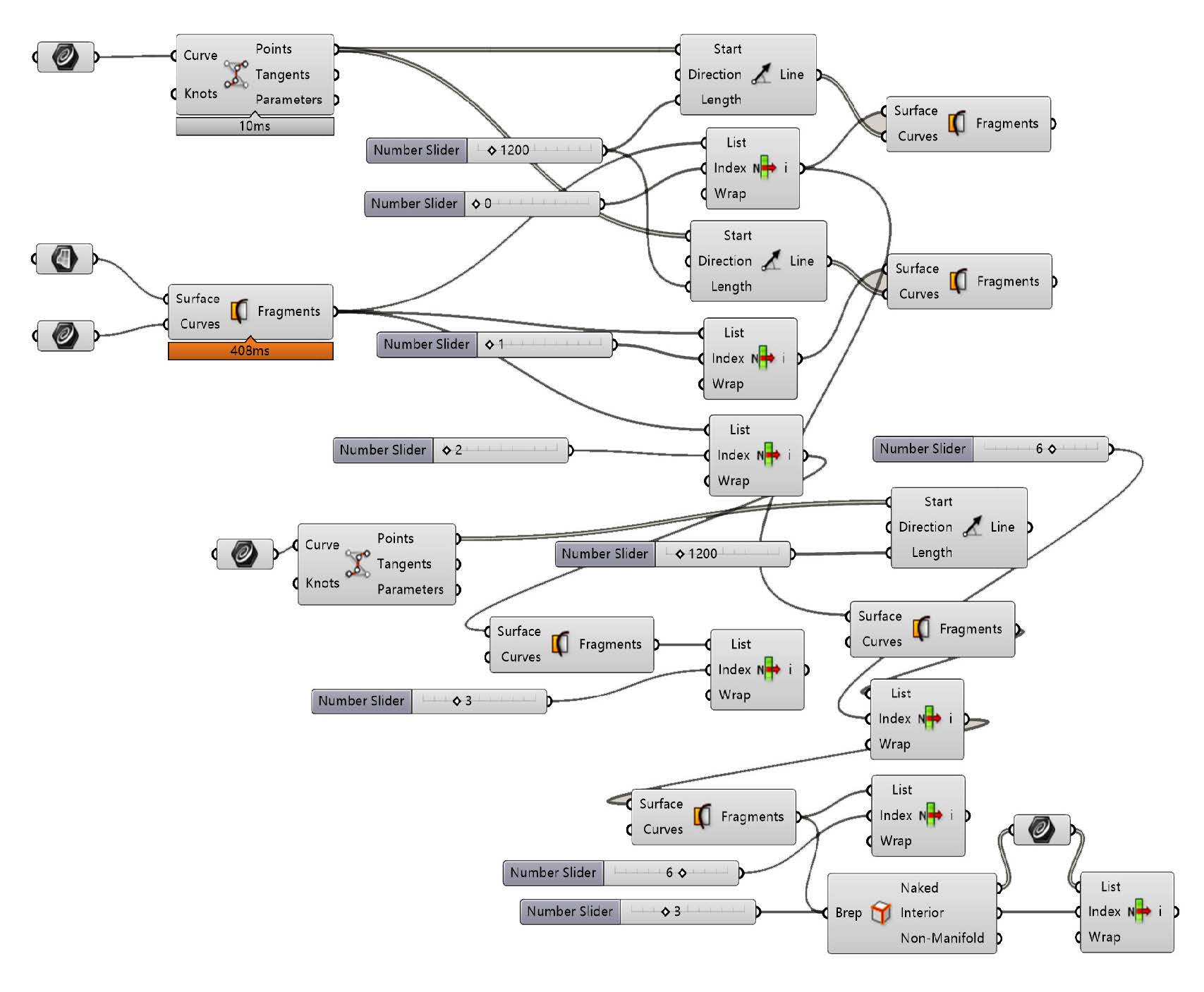
Shell Generation
Printing Segmentation
Design of the Joint with the Steel Frame
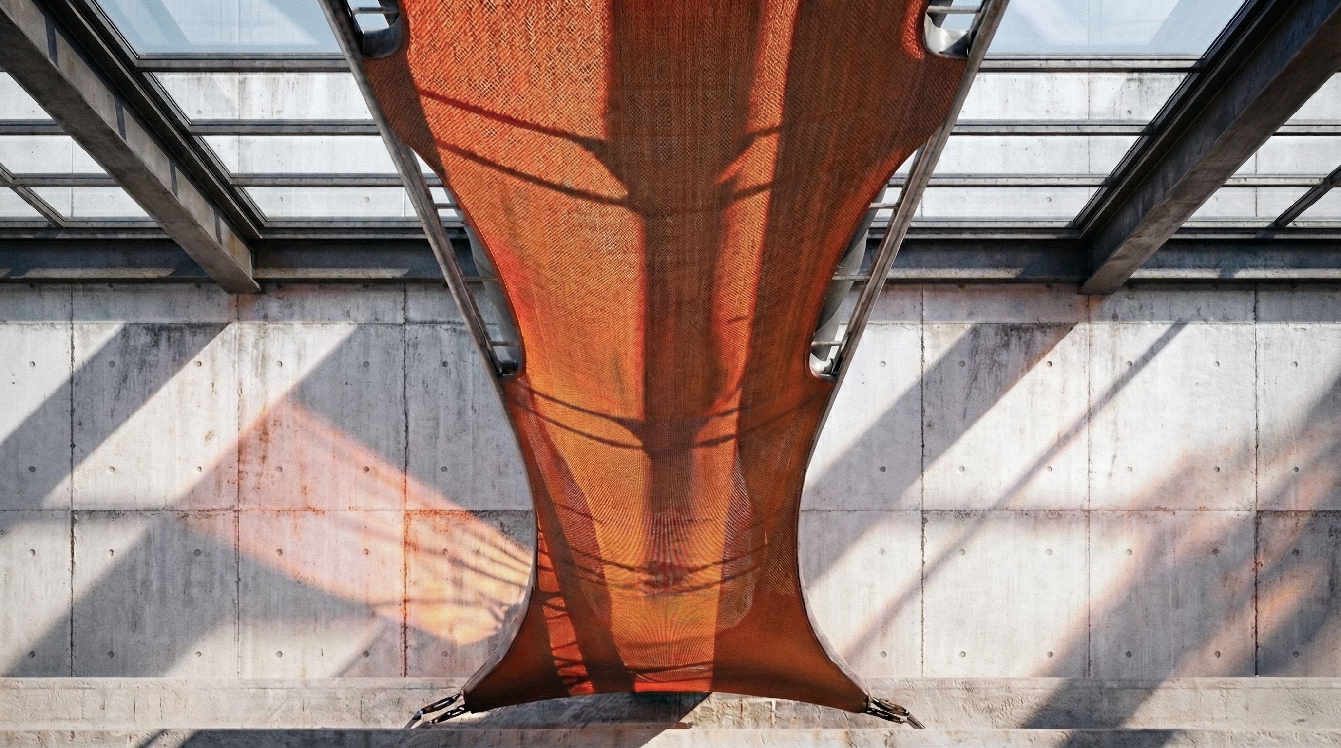
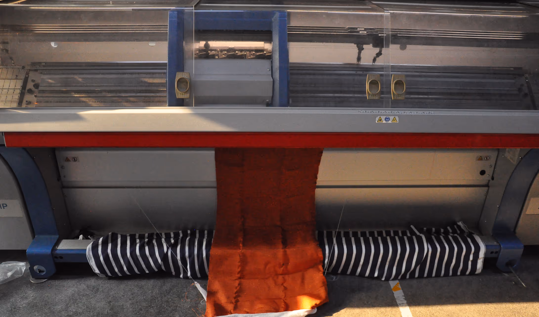
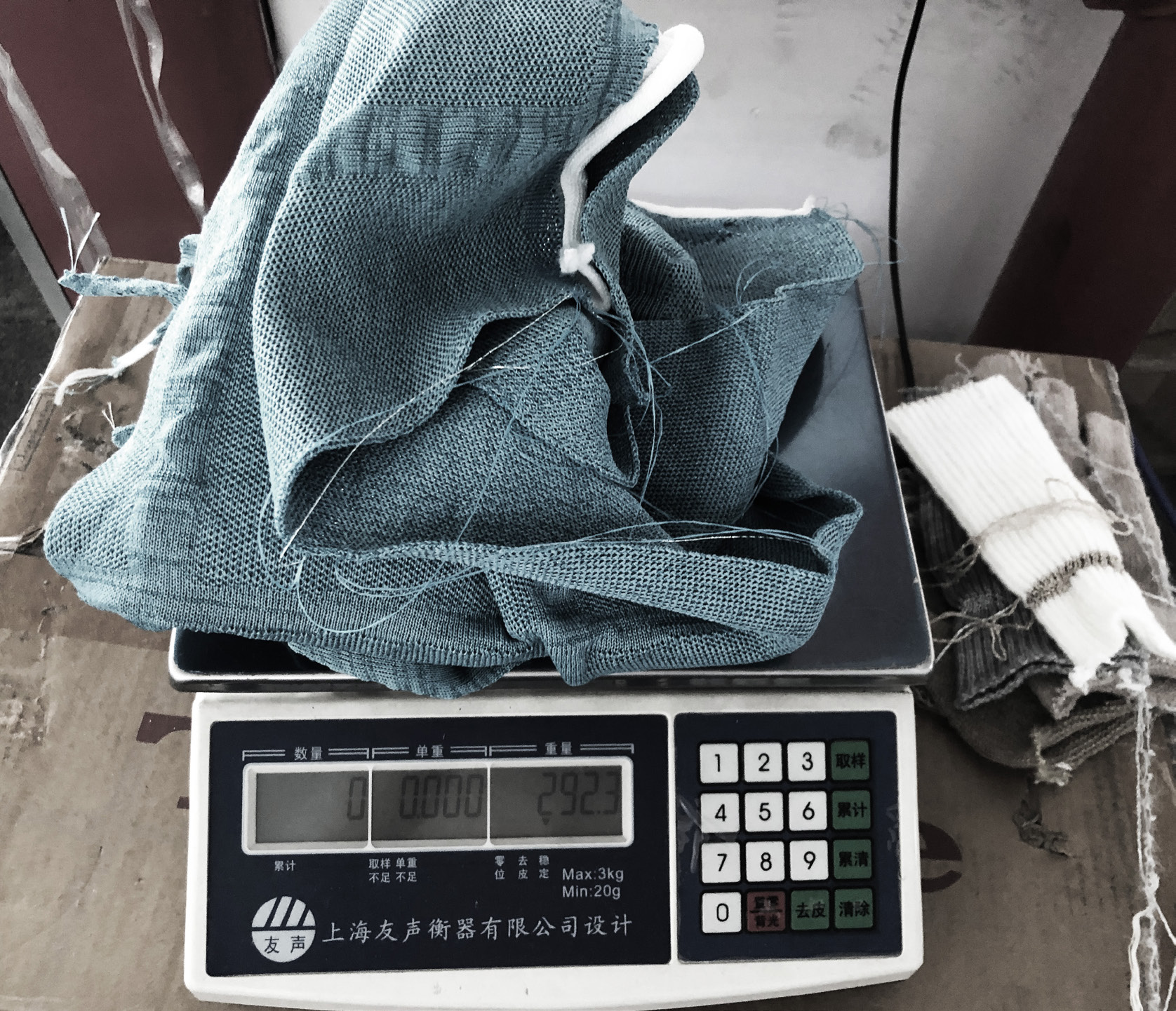
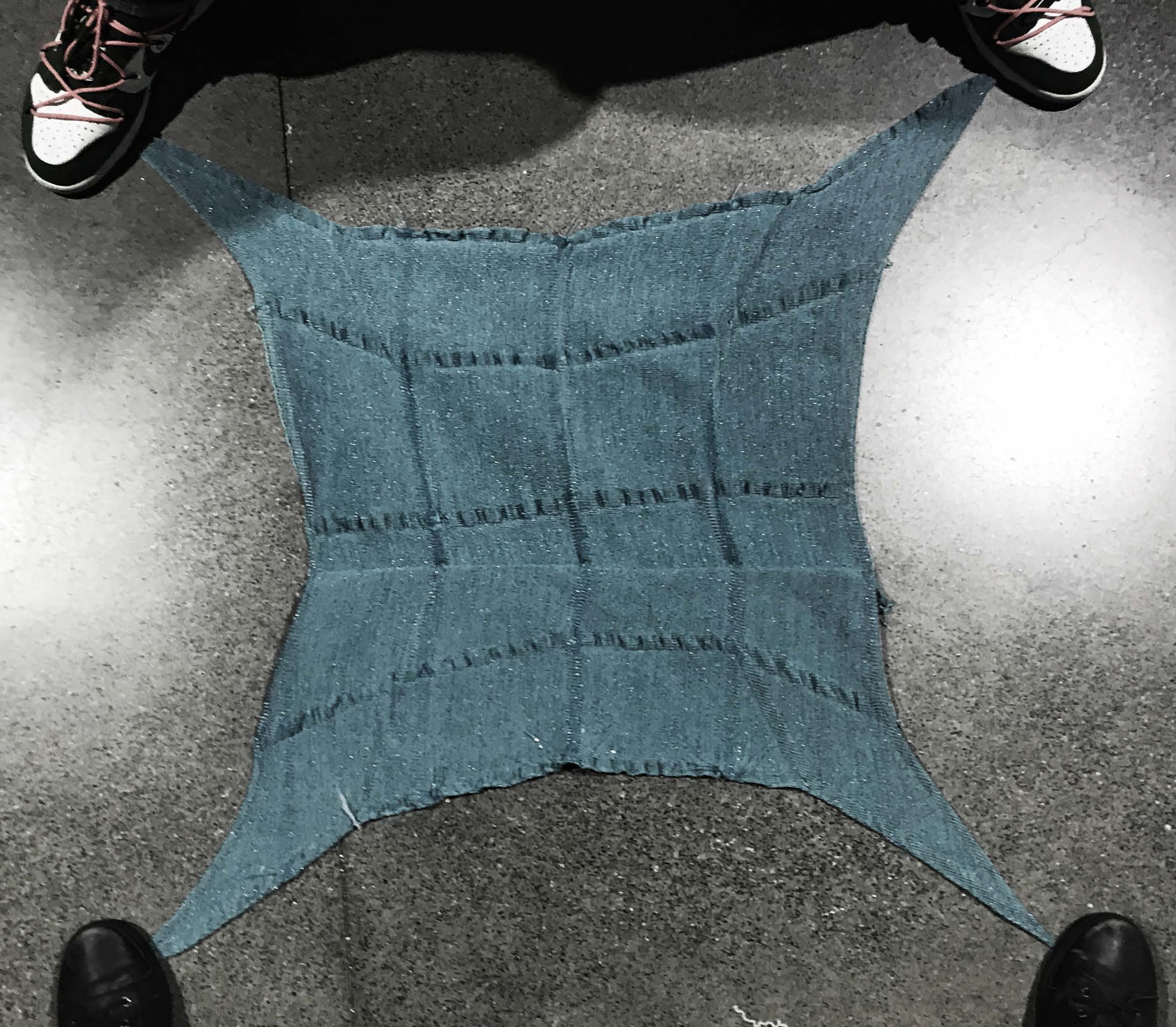
Fabric Tension Tests
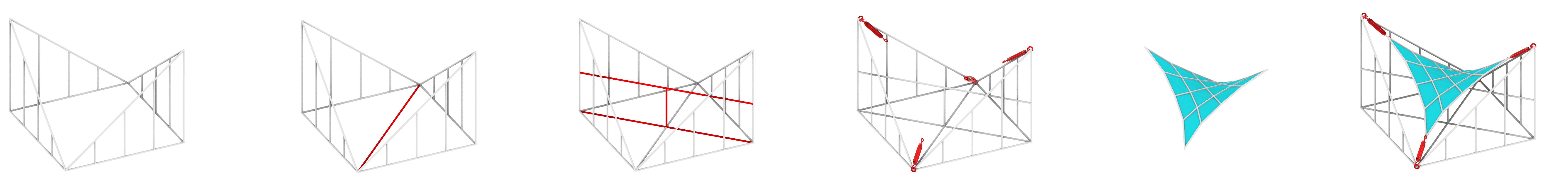
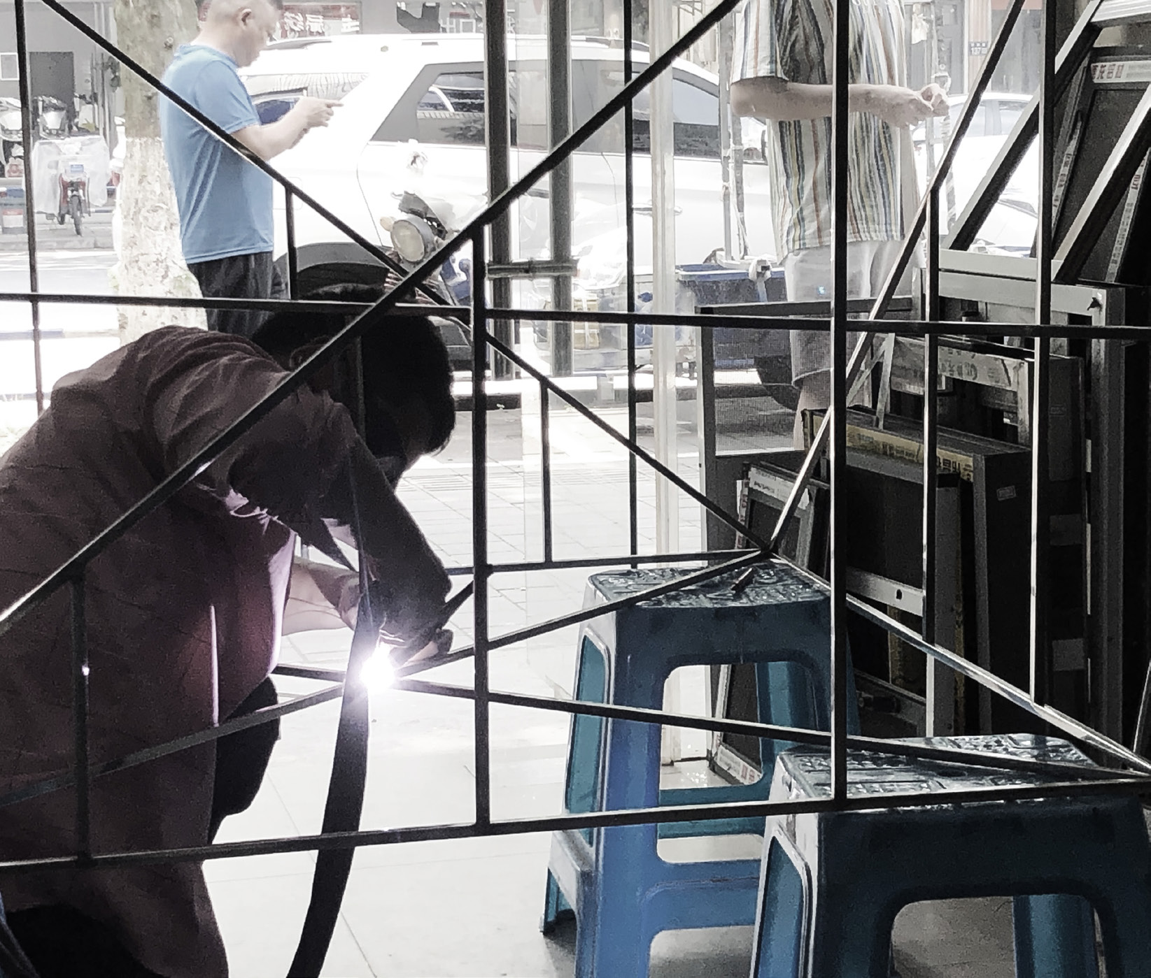
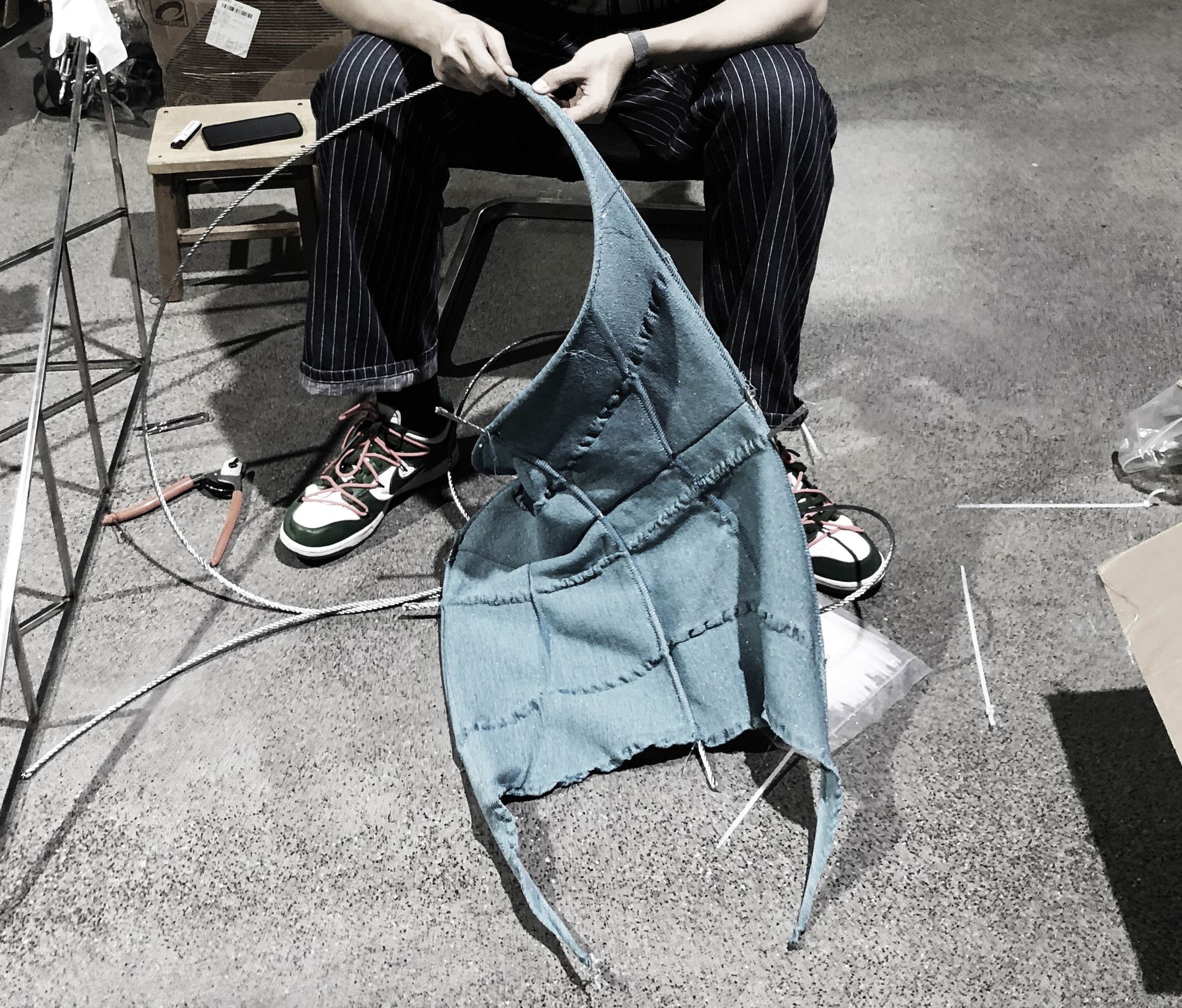
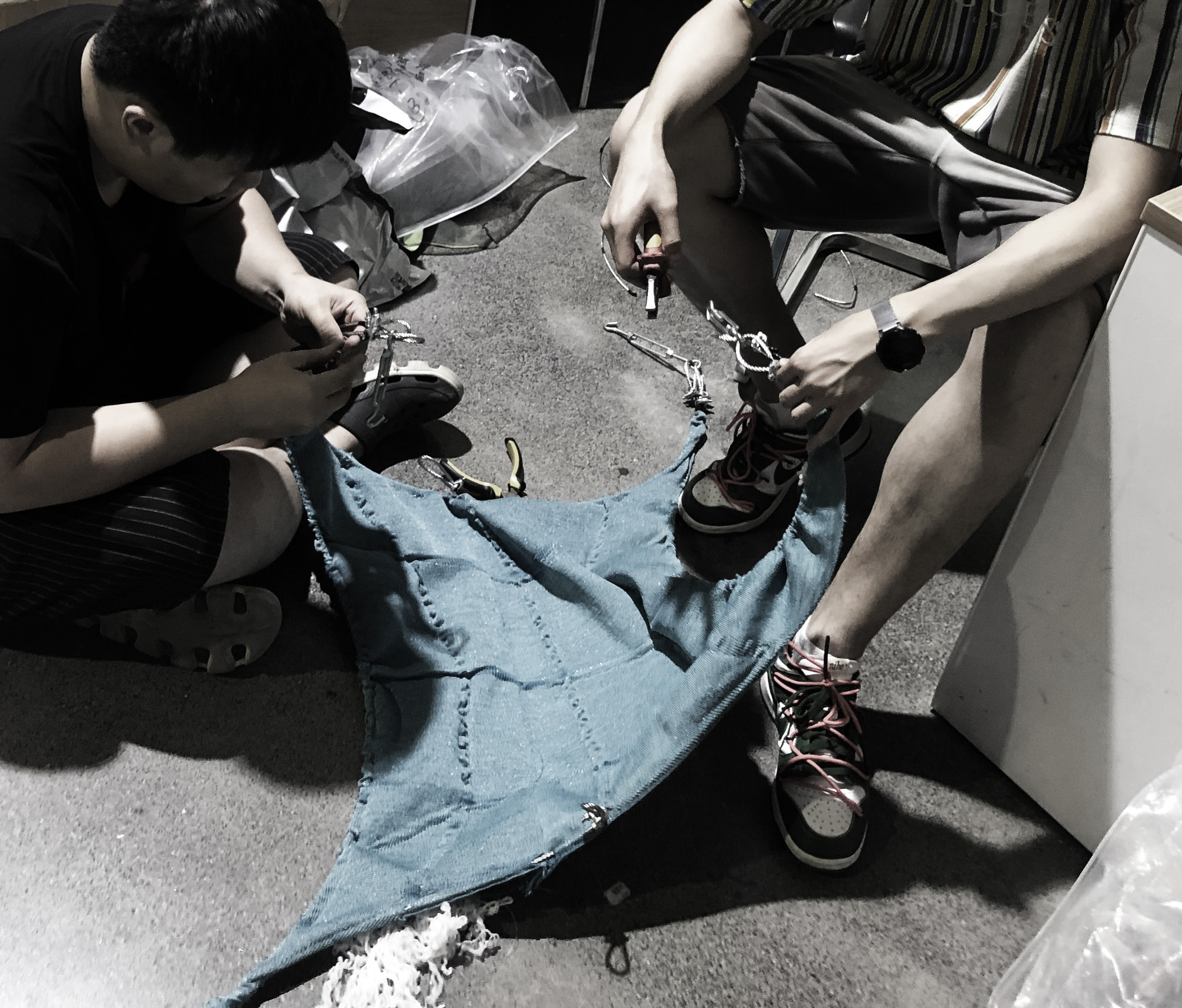
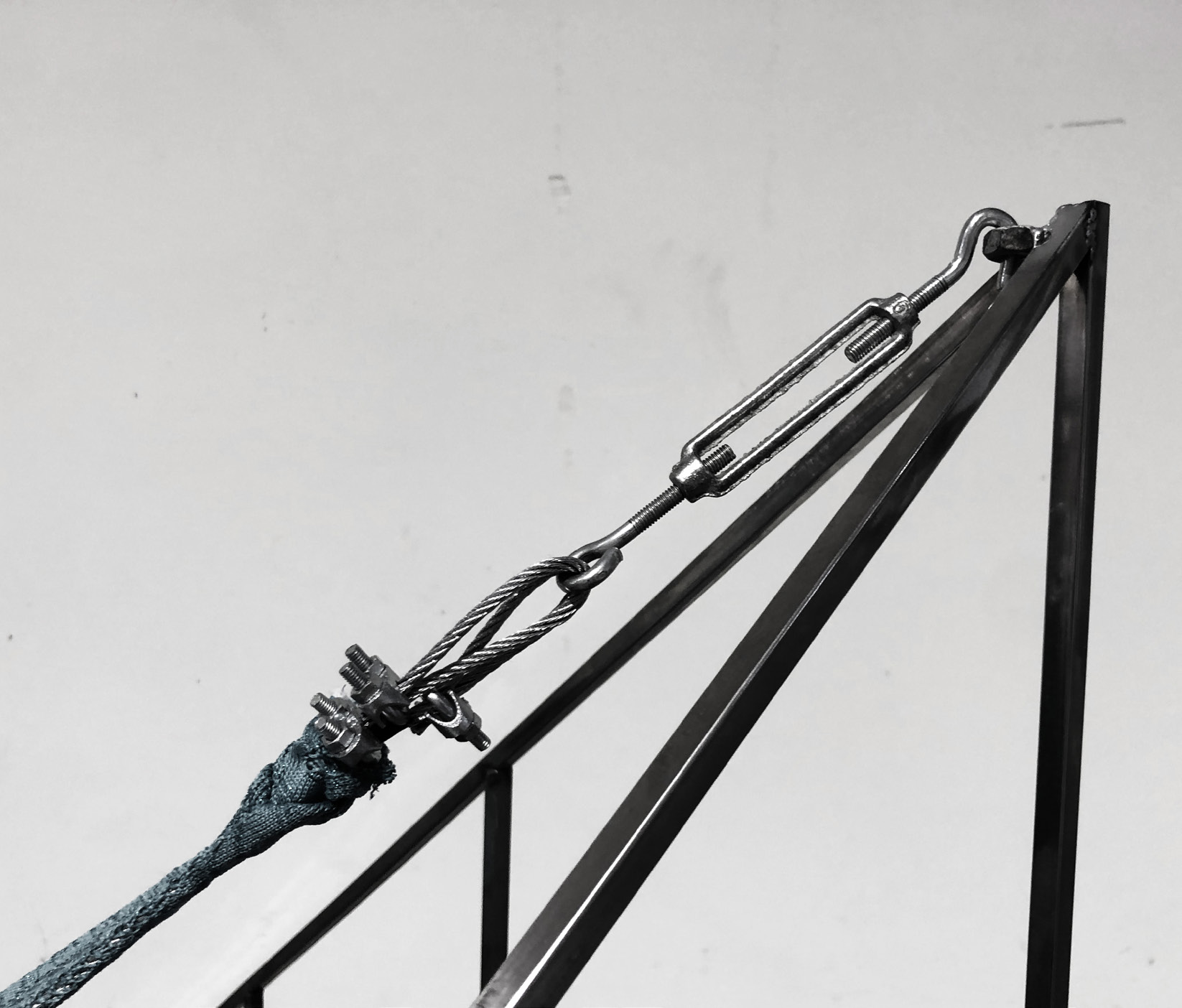
To begin, the shape of the tensioning frame is defined, and turnbuckles are installed at the tension points for fixation. The structure is then reinforced according to the tension points on the underside, threading steel cables through the fabric test sample to form an integrated load-bearing system. Additional reinforcement is applied based on the top tension points. Finally, the load-bearing corners of the woven fabric sample are attached to the turnbuckles using fasteners, completing the test setup.
Testing Process
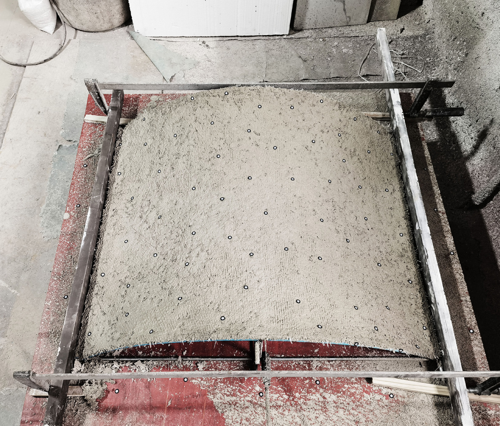
UHPC Casting Fabric Test
Determine the basic frame form
Reinforce load directions using steel cables and rebars
Fit the fabric over the base frame
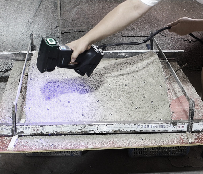
Spray a 1 cm layer of fast-setting cement onto the tensioned fabric
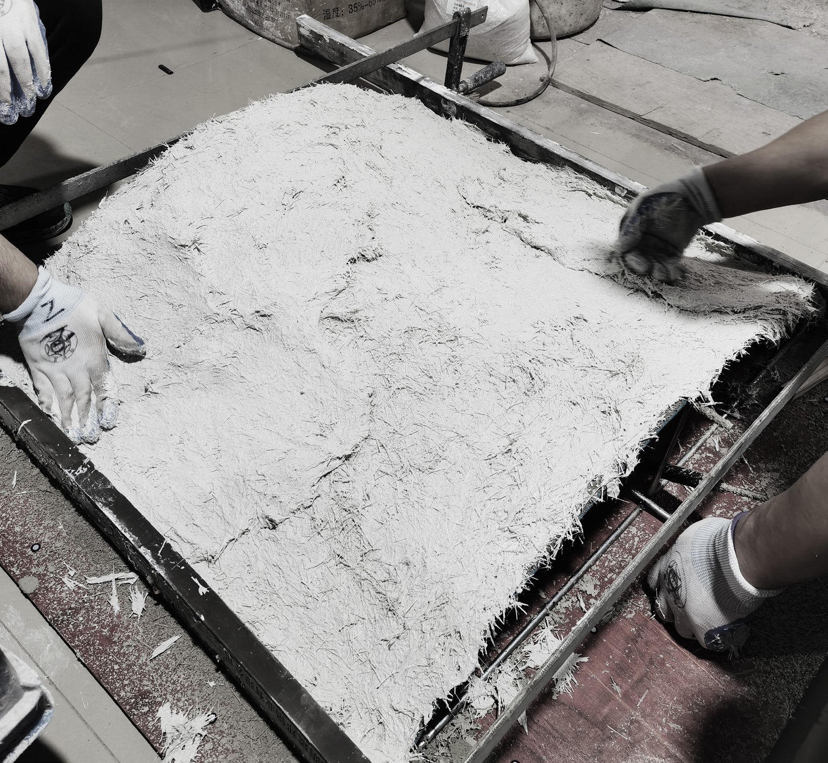
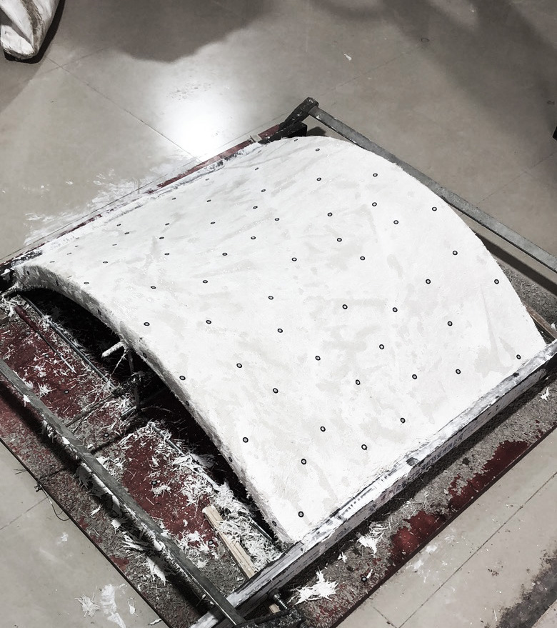
After the fast-setting cement sets, spray 4 cm of UHPC on top
Testing Process
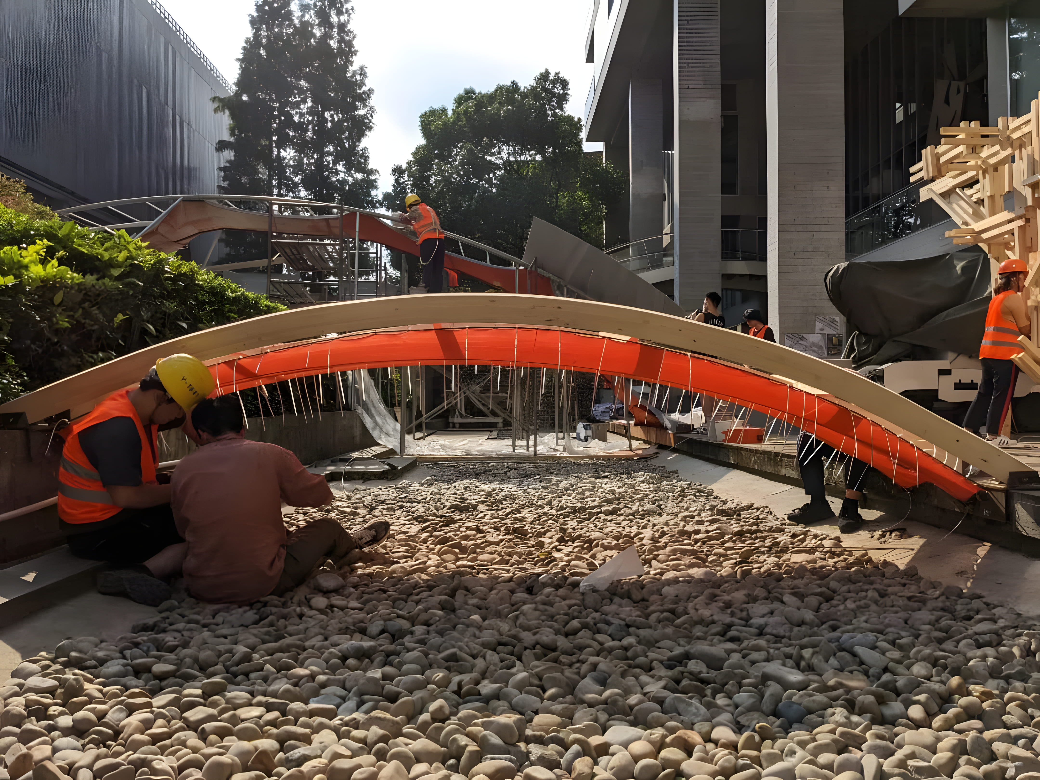
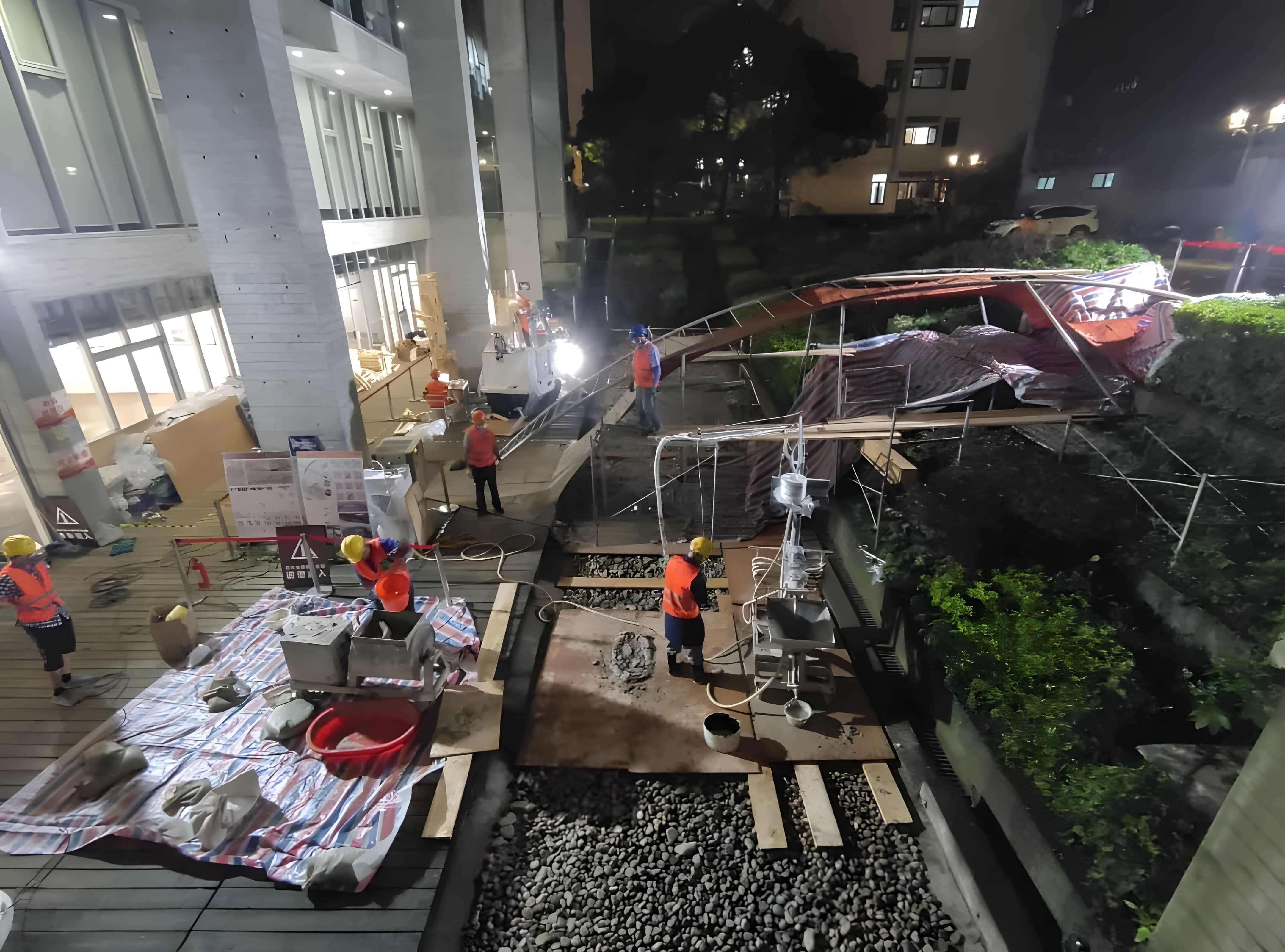
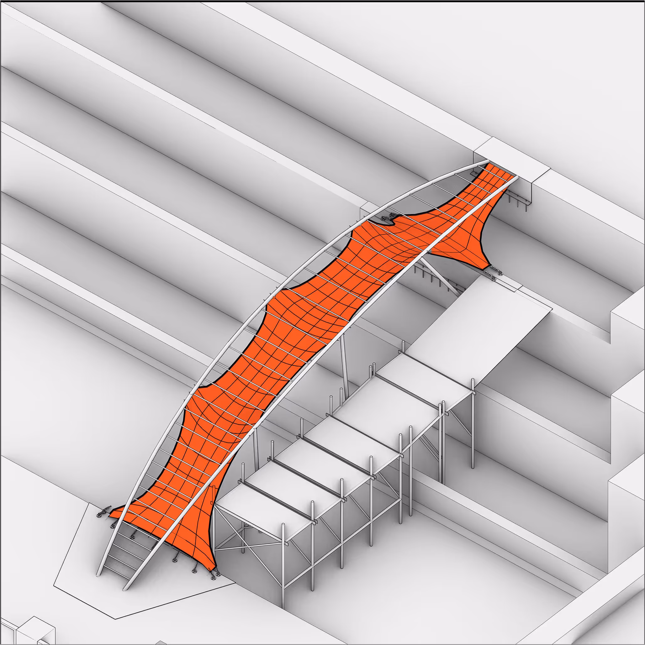
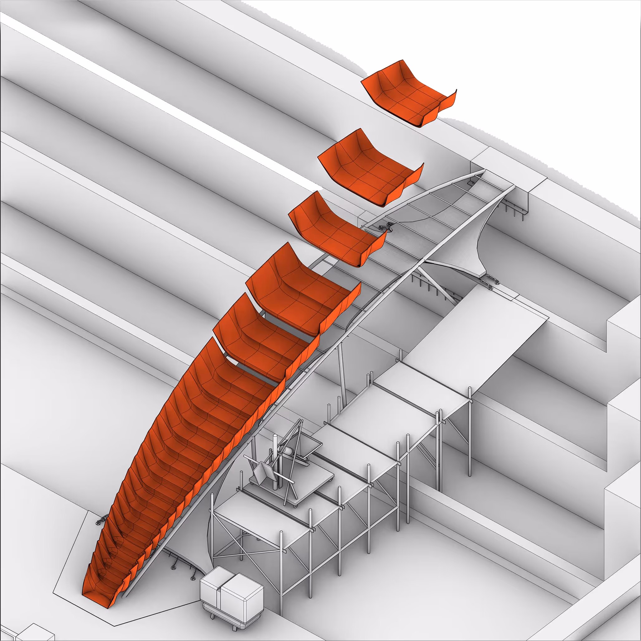
Construction Sequence
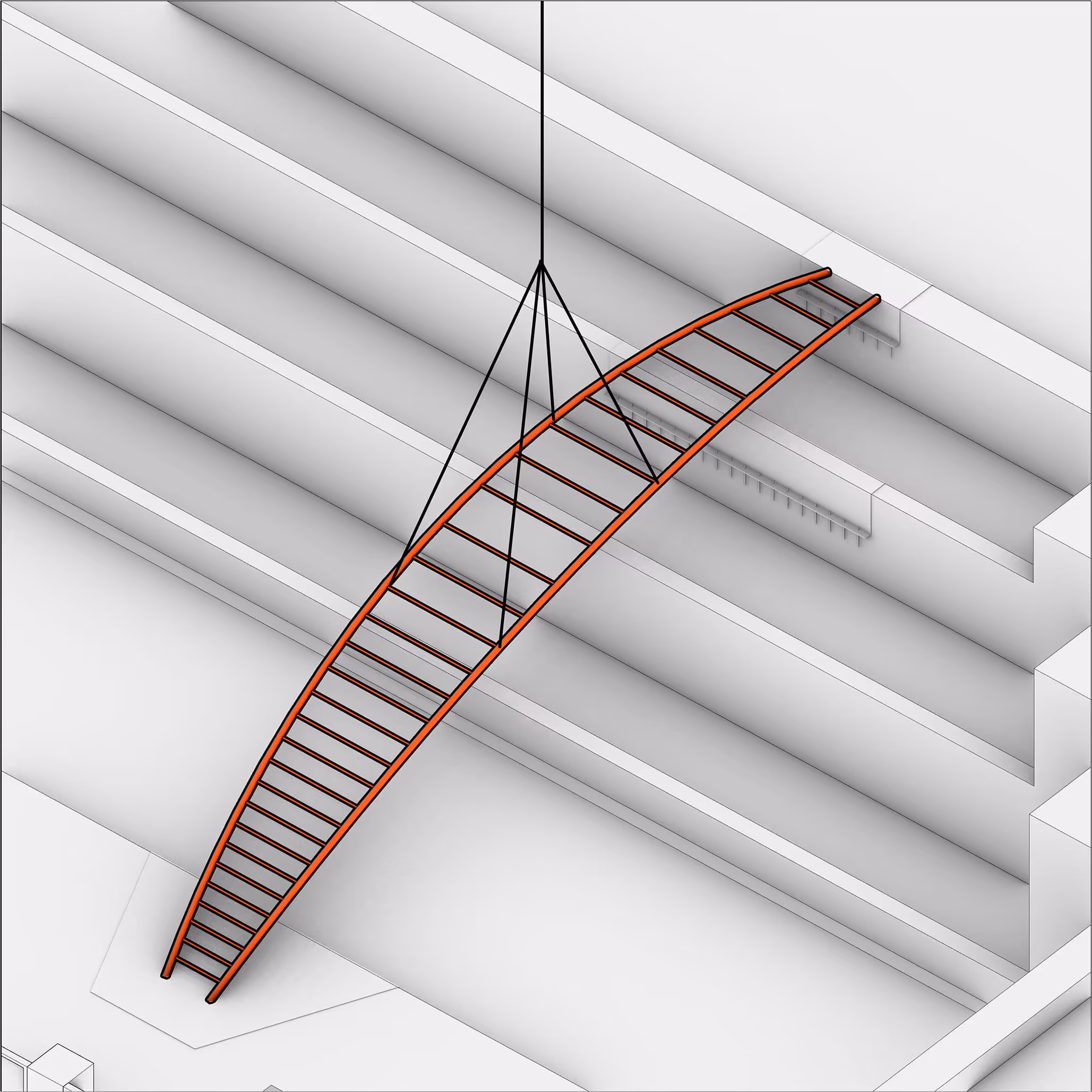
Site Preparation
Install Base Steel Plates
Hoist Steel Framework
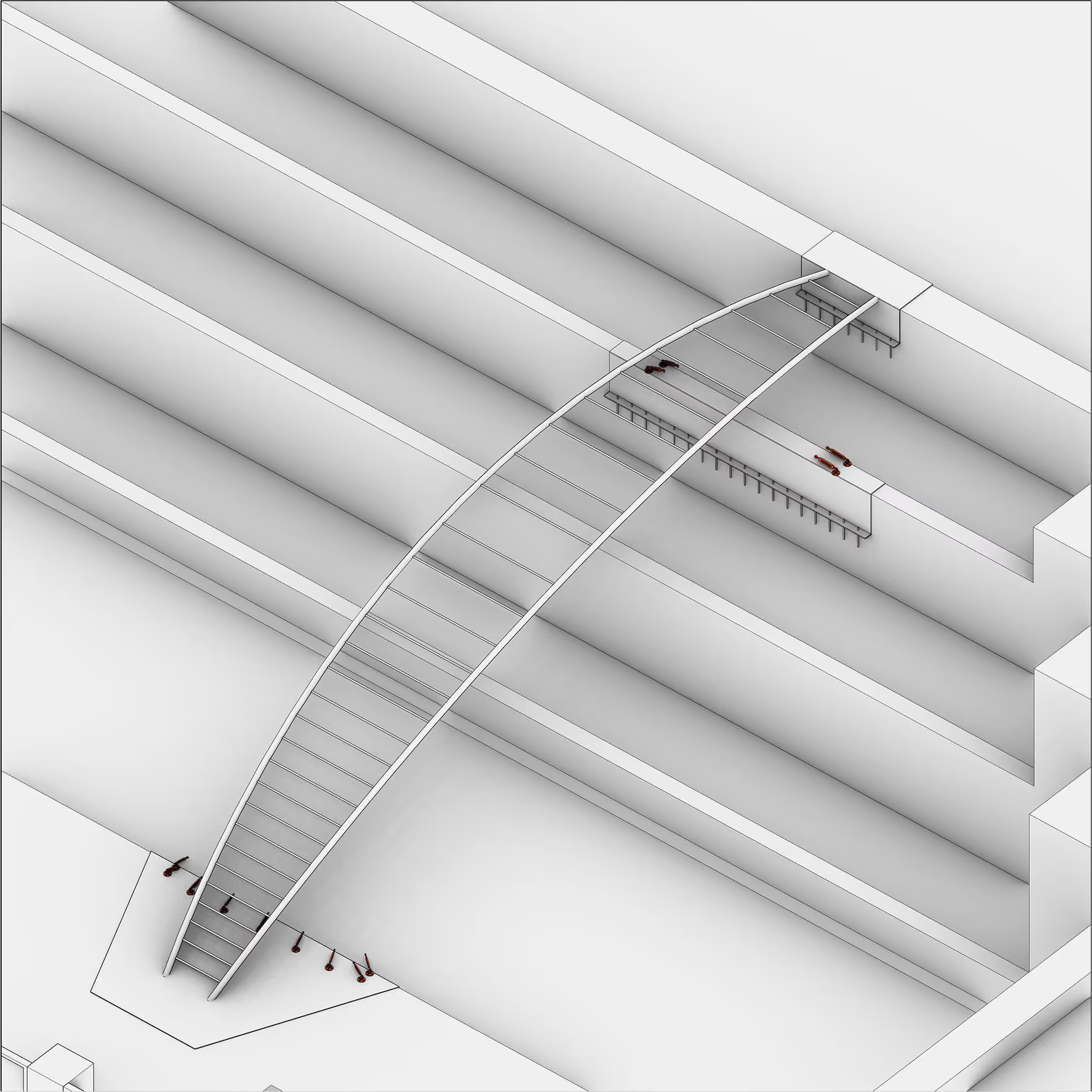
Install Textile Fasteners
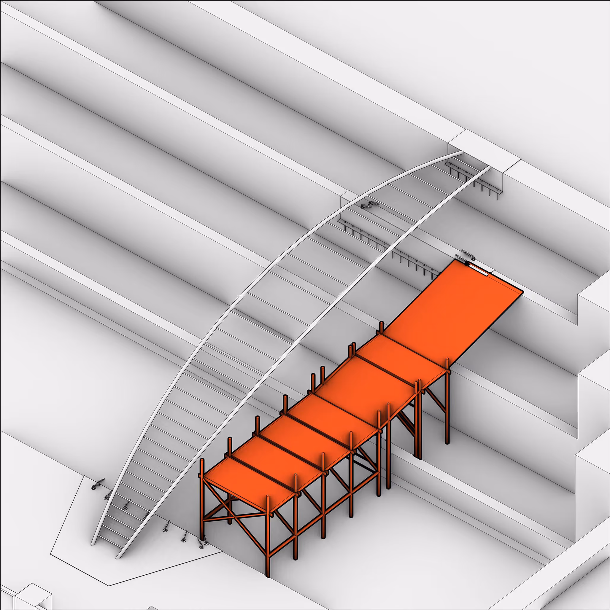
Set Up Scaffolding
Support Steel Framework
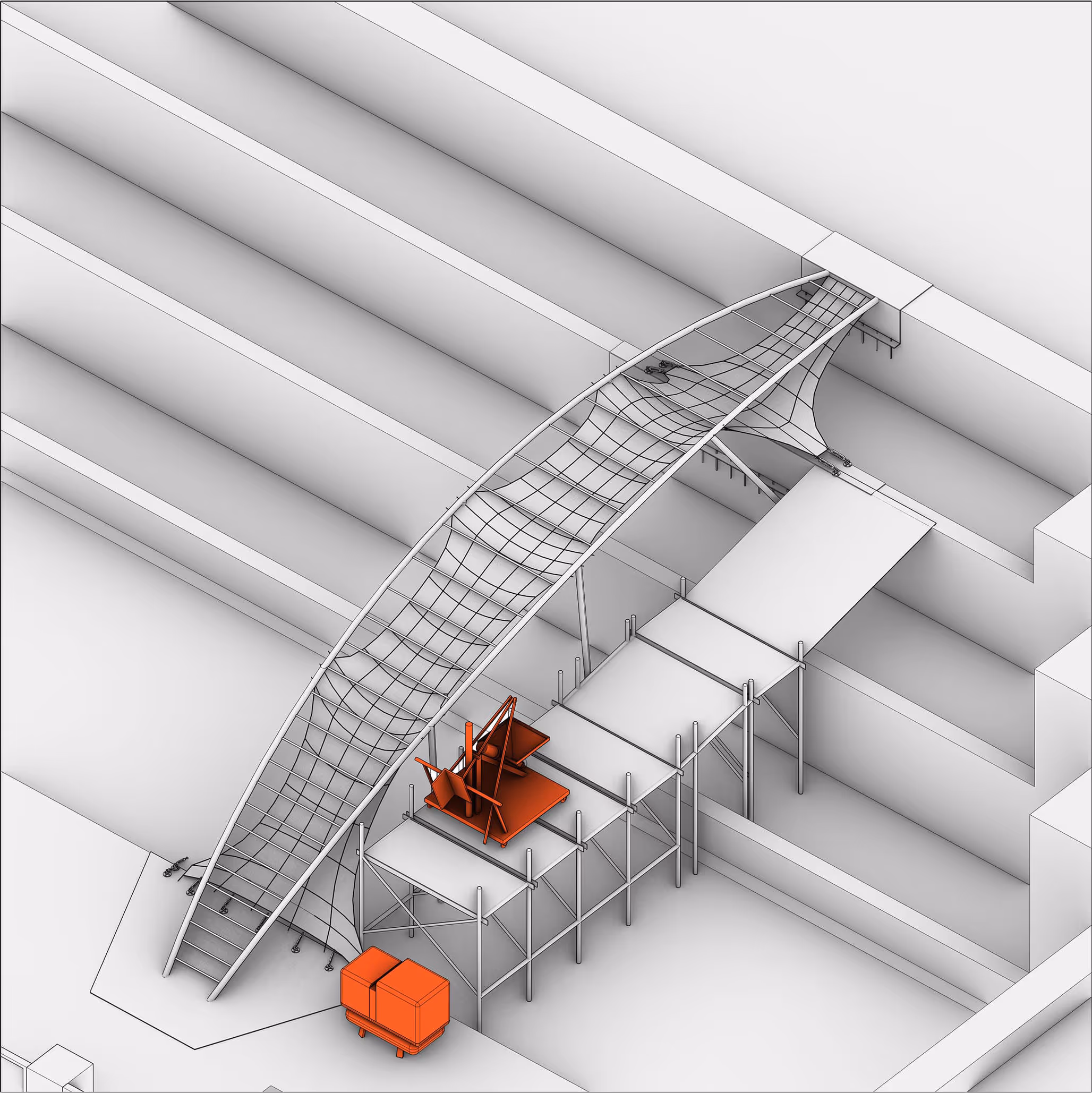
Install Textile Fabric
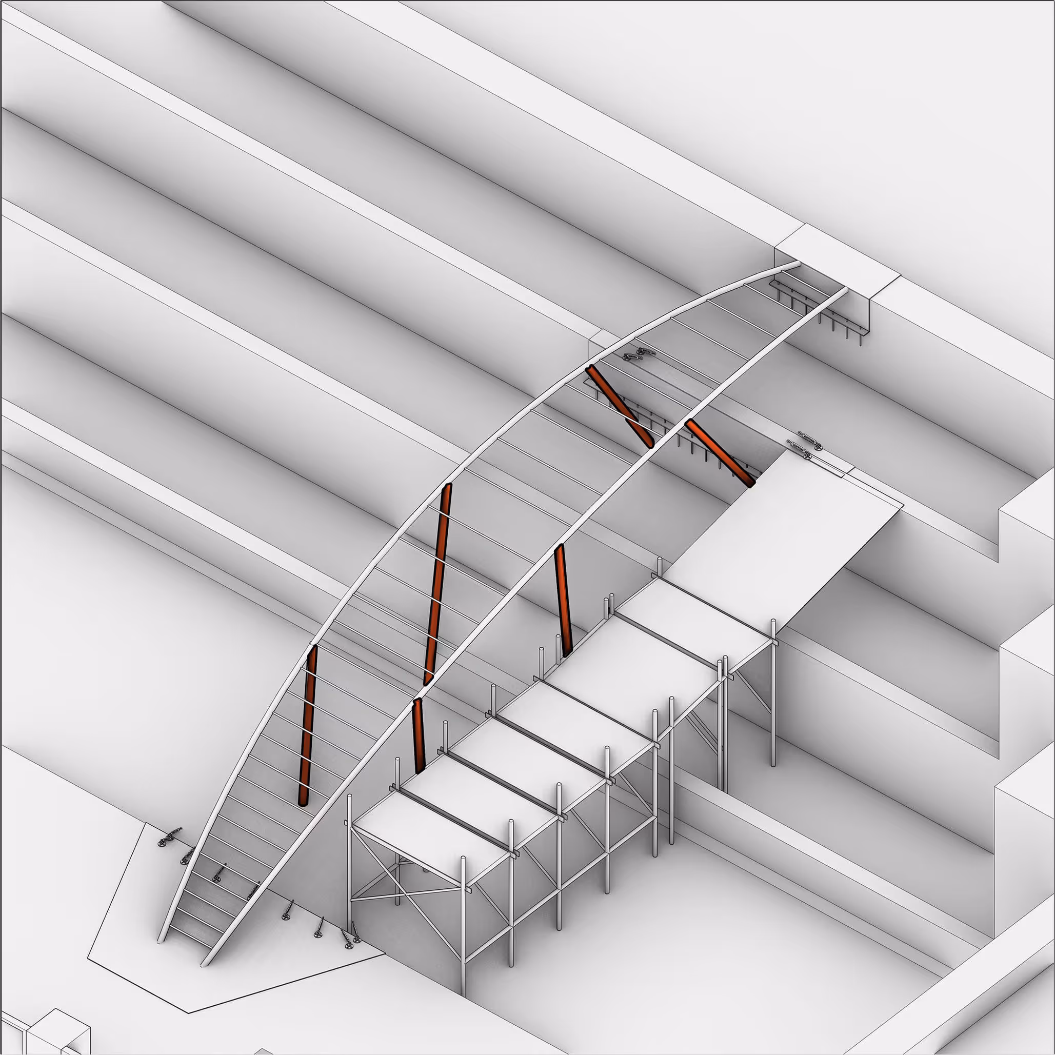
Prepare Shotcrete Machine & Ready-Mix Concrete
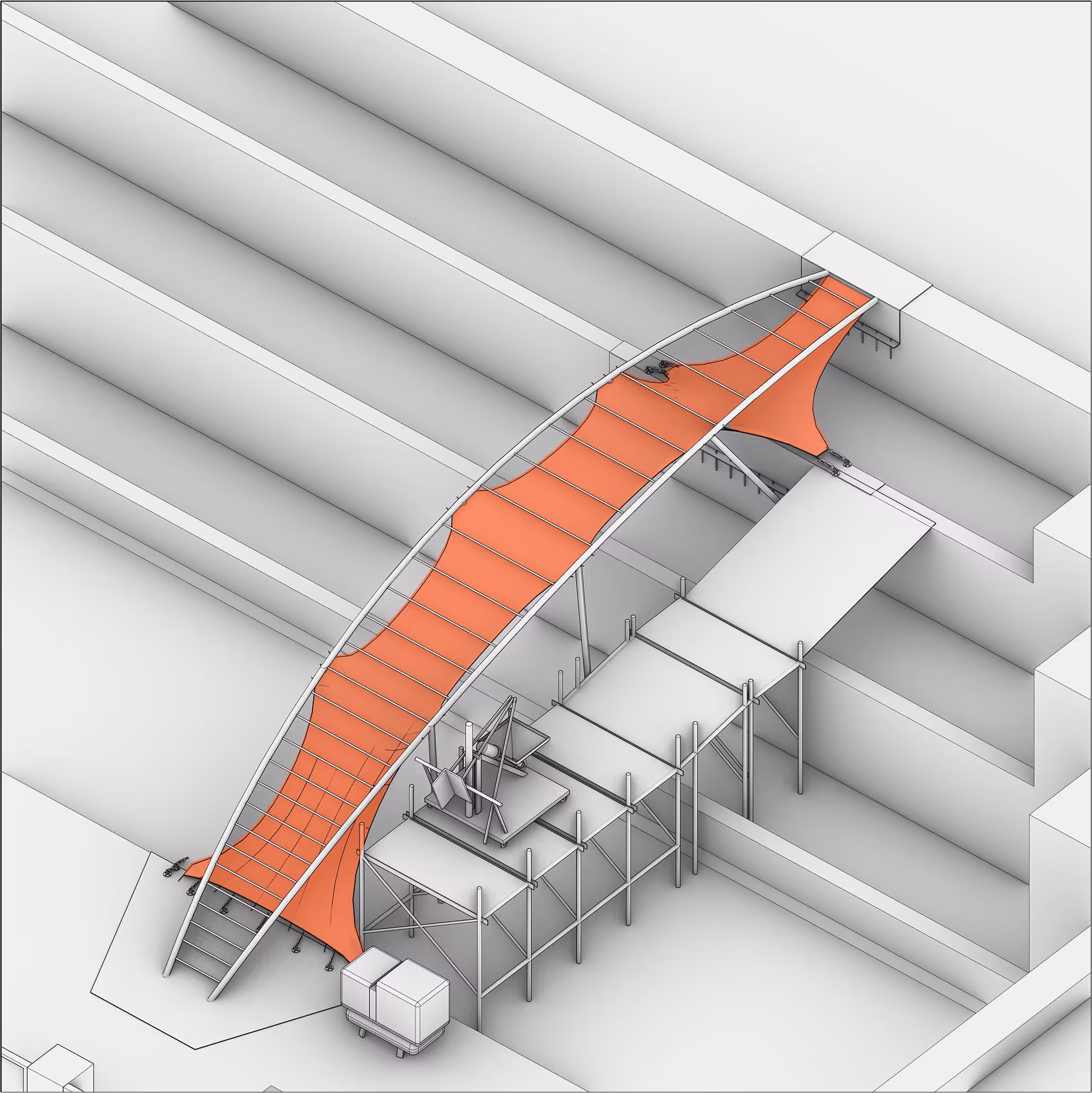
Spray First Layer of Rapid-Setting Mortar
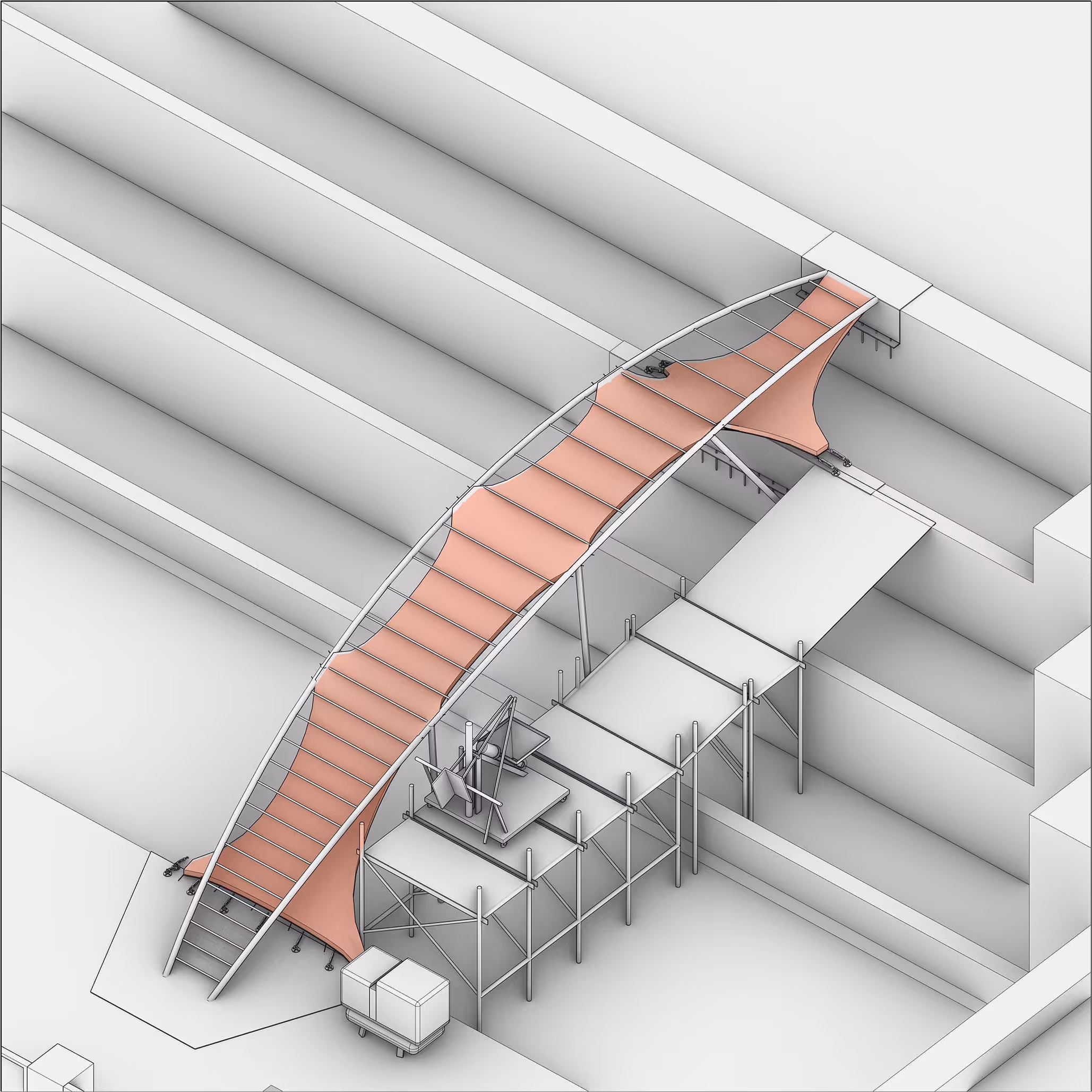
UHPC → Spray UHPC over the Rapid-Setting Mortar
Install Stair Treads
Finish After Cement Curing